During my Track and Field training sessions, my coach often expressed his desire to have a more precise way of measuring an athlete's performance. However, living in a third-world-country means that shipping from the US is expensive and sports clubs and educational institutions do not have precise timing systems as a funding priority.
I had been working on line-follower robots with Arduino for some time, so I realized that an affordable, wireless and precise laser gate timing system made of easy to find components should be possible. Accounting for the different prices across the world, absolutely all of the components and parts needed for the complete system should cost around 100USD. This is a major price difference with other systems, considering that it has a very decent precision and has a wireless range that exceeds almost any Track and Field oval in the world.
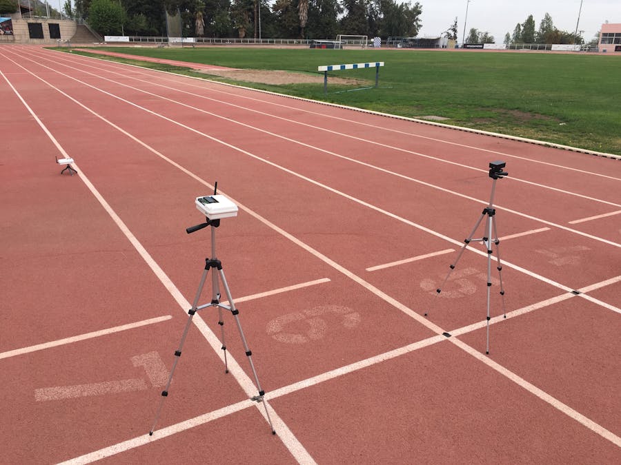
The system consists of two finish line modules and one start line module.
In the finish line, you will have an Arduino UNO, nRF24L01+ Transceiver, LED button pad, photoresistors, LEDs, plastic enclosure, and tripod together with my Finish Line PCB. This module acts as the master, from the LED button pad you will decide when to start the timer.
On the opposite side of the track, you will have a laser that is aligned with the photoresistors. You can either buy a Keyes laser module, a 3.3V regulator, a 9V battery, and my Laser Module PCB, or you can provide your own laser pointer. What matters is that the laser is in a steady position and provides enough light.
In the start line, you will have an Arduino UNO, nRF24L01+ Transceiver, speaker, LEDs, plastic enclosure, and my Start Line PCB. This module is in constant communication with the master and uses an LED to inform the user that it is still connected. When measuring time, the LED will change color.
How it worksFirst, you will set the module on its final position, and follow the prompts that appear on-screen. The photoresistors will automatically calibrate to the ambient light conditions, but it is important that they are inside the plastic enclosure, getting light from a hole in the enclosure. The master module will automatically search for another nRF24L01+ in its range, but will only connect if it has the same electronic "signature", a number that is different for every single system and is concatenated at the end of every message the master and start line module sends. This way, there can be a hundred of these systems in the same track, but will not interfere with one another, thanks to the signature. The system has a wireless range of 250m+. Even in places crowded with WIFI, the system has no trouble connecting and maintaining a more than decent range.
The master module offers two ways of measuring an athlete's performance. First, MANUAL: this mode sets a stopwatch directly after pressing the start button. Great for athletes that work with coaches.
Secondly, AUTO: this mode allows an athlete to set off a timer that will allow him/her to have a scheduled start time, allowing time to walk from the finish line, where the master module sits, to his/her preferred start line.
When the master sends a stopwatch message, the startline module will shout: On your marks! Get set! PEEEEEEEP!. The stopwatch will begin in the same fashion a real race measures time and will stop when the athlete crosses the laser-gate at the finish line.
The system will provide accurate time-keeping and show the athletes time on the LED screen. When done, just press SELECT and try to beat it next time.
Please watch, as the video will show a track demonstration and a look inside each of the modules which will help explain how it works.
Wiring for the Arduino UNO in the Finish Line Module
Connect from Finish Line PCB
- A1 = Photoresistors
- A2 = Photoresistors
- A3 = green LED
- A4 = blue LED
- A5 = red LED
Connect from nRF24L01+ Adapter
- CE = 2
- CSn = 3
- SCK = 13
- MISO = 12
- MOSI = 11
Connect LCD Shield
Wiring for Arduino UNO in the Start Line Module
Connect from Start Line PCB
- 4 = green LED
- 5 = blue LED
- 6 = voltPin
- 3 = speaker
- A5 = voltLED
Connect from nRF24L01+ AdapteR
- CE = 9
- CSn = 10
- MISO = 11
- MOSI = 12
- SCK = 13
Here are some close-up images of the modules.
Finish Line Module
Start Line Module
Laser Module


_ztBMuBhMHo.jpg?auto=compress%2Cformat&w=48&h=48&fit=fill&bg=ffffff)


_3u05Tpwasz.png?auto=compress%2Cformat&w=40&h=40&fit=fillmax&bg=fff&dpr=2)
Comments
Please log in or sign up to comment.