


Hardware components | ||||||
 |
| × | 1 | |||
| × | 1 | ||||
 |
| × | 1 | |||
 |
| × | 1 | |||
| × | 1 | ||||
| × | 1 | ||||
Software apps and online services | ||||||
 |
| |||||
Hand tools and fabrication machines | ||||||
 |
| |||||
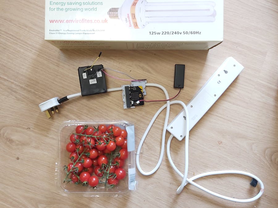
I have begun looking at how to build an automated grow room. There is great demand for this sort of thing, both in the EDTECH world and also in the general population... who doesn't want fresh tomatoes in the middle of winter?
Grow rooms require a strong light: one powered by mains electricity. To automate a grow room I therefore need to control an appliance that is plugged in to mains - I need an on-off switch that I can manage using code.
This project is part 1 of the grow room: it shows how to turn mains power to ANY appliance on and off using a micro:bit and some XinaBox kit. It is key to my grow room project, but it is also a very useful and generic set up that could be used for all sorts of automation projects (some ideas listed at the end). And once you can use a micro:bit to switch the relay on or off, it is a very simple step to add Wi-Fi and control it via IoT, as I will show you in part 2.
Using an extension cableI used an extension cable in this project for two reasons:
- ... If I control the extension cable then I can turn several appliances on and off at the same time.
- ... If I mess up I lose an extension cable and not the appliance
The wiring and approach used here would work just as well if you connect the relay to the power cable attached to an appliance.
How a relay works, for first timersFYI this is my first time using a relay. I had help from my oft-times collaborator and friend @KalbeAbbas - KJ... thanks :)
The relay I used is shown below. Yours may be different but the labels should be the same or similar. My relay works with a 3.3V power supply, which allows me to use my BBC micro:bit without needing to add in a 5V power source.
A relay has an electromagnetic switch which is used to turn a power supply ON or OFF. Here's what we will use that for:
- We will connect the relay to our mains extension cable (on the left side in the image above).
- We will connect our micro:bit to the relay (on the right in the image).
- We will use the micro:bit to activate the electromagnetic switch in the relay.
- This electromagnetic switch will control the flow of electricity through the mains extension cable.
- The micro:bit will therefore control the flow of electricity through the extension cable.
The micro:bit will also provide power to the relay: the relay needs 3.3V to power its electromagnetic switch.
Connecting the Extension Cable to the Relay:I used a cheapo extension cable which I chopped as shown:
To connect the extension cable and the relay I used the following circuit:
As the diagram shows, I need to slice just 1 cable and run it through the relay in the N0 and COM ports. The cable to use is the live one - colour coded brown in the UK.
Goes without saying: exercise GREAT caution when working with mains electricity. The author and Hackster accepts no responsibility for any injury or damage you might cause / incur.
NB: the image above shows the relay connected to the cable: it is NOT SAFE to leave the relay like this and plug the cable into your mains.
NOT SAFE AT ALL.
A housing for this is essential - see the later section titled Safety First.Connecting the micro:bit to the Relay:
Connect your xChips as shown in the image below (on the left), then slide in your BBC micro:bit:
Next get some wires and connect the IX01 to the relay as shown below:
Notes:
- The GND and VCC pins on the IX01 are used to provide 3.3V power to the relay... the relay needs this power to activate its electromagnetic switch.
- The TXD pin on the IX01 sends data to the relay (either "1" or "0").
- The TXD pin on the IX01 is PIN0 on the micro:bit. Similarly we could attach the RXD pin, which is controlled using PIN1 on the micro:bit.
Here's a better pin diagram:
With everything wired up, all that remains is to write some code for the micro:bit that will prompt the relay to turn ON and OFF.
- To turn ON the mains power we need to send the value 1 to the relay
- To turn OFF the mains power we need to send the value 0 to the relay
We will implement this using button clicks:
- When clicked, button A writes 1 to PIN0, which turns the relay ON;
- When button B is clicked it writes 0 to PIN0, turning the relay OFF.
The code below is all we need:
Using mains electricity is no joke - you need to take real precautions.
What I did was build an enclosure for the relay that makes it impossible to touch any live wires. I used an old business card box, because I had one lying around and it was a good size. Old boxes, polymorph, folding cardboard, 3D printing - there are loads of ways to build a housing for the relay, and you should do so before running power through it. Here's some pics of my housing:
You will notice that I put 3 wires outside the box. These wires connect to the DC terminals ("DC-", "DC+" and "LN1") of the relay and allow me to connect the micro:bit + IX01 without having to get anywhere near to the relay.
Run and TestBe cautious when testing.
Make sure the code is loaded on your micro:bit and that everything is plugged in properly. Power up and run the micro:bit, then push A and B buttons to test the setup. When you press A the extension cord should turn 'ON' and any appliances attached will begin to draw power.
Here's some pointers that might help:
- This depends on the relay you use, but when the DC power supply is connected properly you should see an LED light indicating the relay is powered up
- When the state of the relay changes you can usually hear a satisfying clicking sound.
- My relay shows a green LED when it is connected and ON, and a red LED when it is OFF.
This setup allows me to turn on a grow light using the buttons on the micro:bit. But I might just as well use the on / off switch in the socket on the wall!
What I have actually achieved here is the ability to turn the light on and off in CODE. It is relatively trivial now to upgrade the switching method:
- One option is to add a second micro:bit and use that to communicate with the first via the built-in radio. You could switch the extension cord on and off remotely from the second micro:bit using radio comms.
- I could attach a light sensor to the micro:bit - the SL01 from XinaBox would work perfectly. Then when the light level drops below a certain threshold I could switch the light on.
- I could include a fan and a weather sensor: turn the fan on when humidity surpasses a threshold.
- My plan is to add a Wi-Fi module to the micro:bit and control the extension cable from an IoT platform. This will be the focus of Part 2, which I will release in September some time.
I am also going to look at whether I can control each socket in the extension cable separately - turn each on and off individually from code. If there is a simple solution I will write that up.
I have a completely separate use case for the same setup that I might consider implementing when lockdown is over: I use a Blink home security system, which includes cameras that turn on when motion is detected in my house - I can watch the cameras in real time over the Internet. It has occurred to me that having to watch burglars defile my home would be quite frustrating. With this setup (and the IoT enabled switch) I could go all Home Alone on them, turning appliances, and maybe the odd death trap, on and off while watching and recording their terror!
Thanks for reading and please look out for Part 2 :)
This project is meant to be easy to read and relatively simple to implement. It shows you how to achieve a useful outcome without labouring on irrelevant technical details. If you like this style please check out my book: Beginning Data Science, IoT and AI Using Single Board Computers.


Comments
Please log in or sign up to comment.