


Hardware components | ||||||
 |
| × | 1 | |||
Hand tools and fabrication machines | ||||||
 |
| |||||
After many years of use, our favorite programming adapter, the Tag-Connect TC-2030-CTX-NL, finally failed. Discouraged by high prices, we wanted to see if we can make a lower cost version for DIY and really anyone.
We think that the more people using the same programming connector on DIY and open source projects the better. Furthermore reducing the costs of hardware helps everyone.
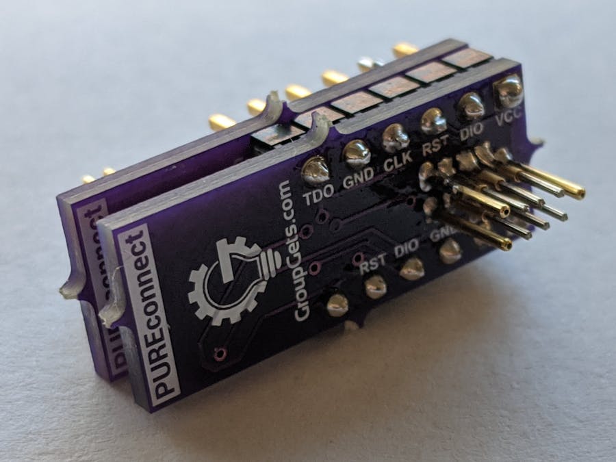
FeaturesThis connector supports adapting to three different programming methods. And really with 100 mil headers any custom pinout as well.
- Standard 10-pin Arm Cortex
- STM SWD 6-pin programming header
- Microchip 5-pin programming header
We knew we wanted to replace our programming connector and we looked into several options before settling on the current design.
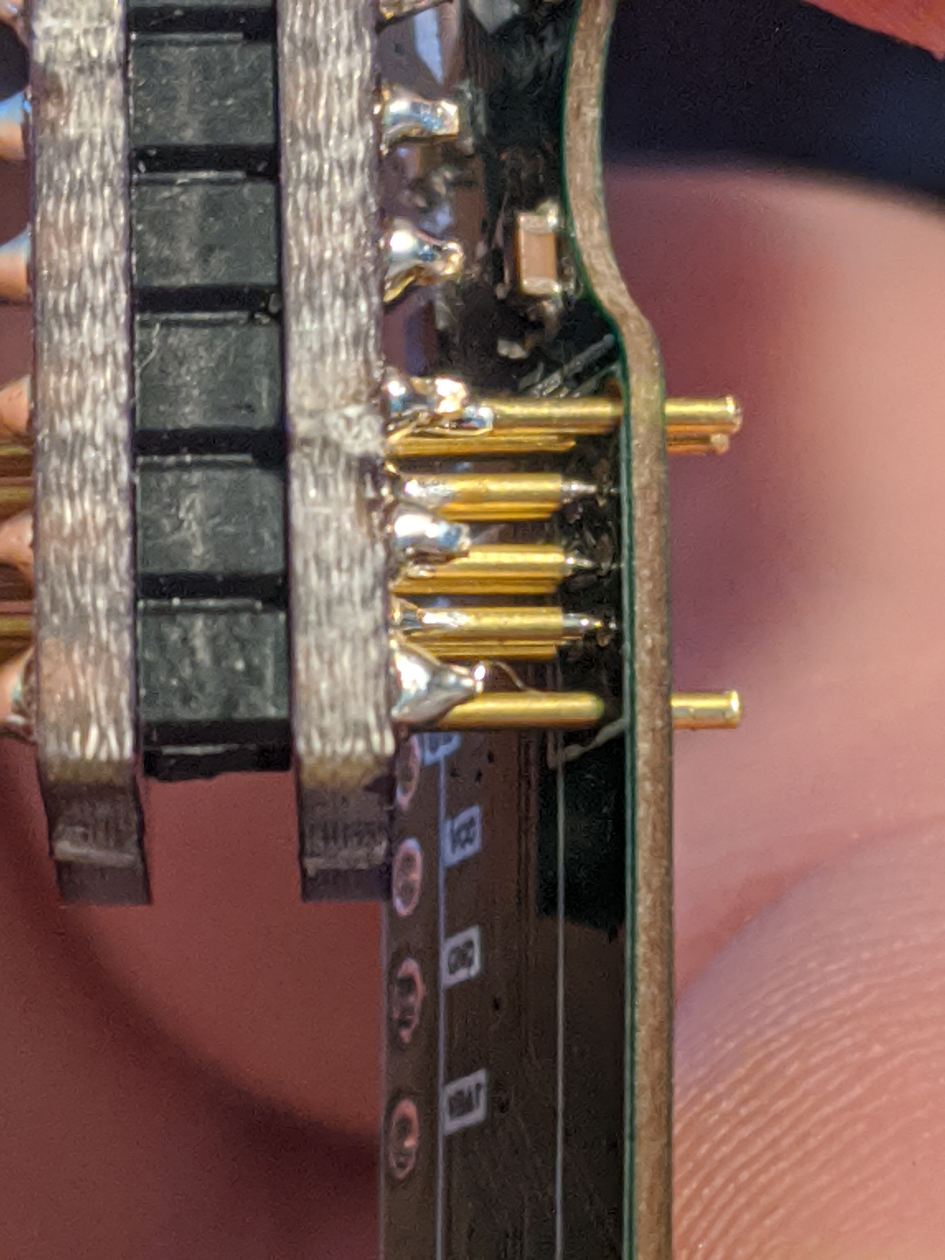
Our first design was focused on a very thin PCB and soldering the pogo pins on the PCB sideways. Although this works fine, it is difficult to assemble with all the pins straight and same height. Reworking the pins was a trial and error process. We didn't want something that was too hard to reproduce, so we looked at a different approach.
The second design was more a less a research effort looking for a spring loaded header with the right pitch and pins. Several connectors were found, yet there were mostly custom orders and required a large minimum to make it worthwhile. Once the costs of the custom connector were taken into account, it would not be ideal price-wise. Also if we wanted to make different pin-outs in the future, then we would be out of luck.
The third and current design is what you see today. We used two PCB stacked together in the past to make a bed of nails for testing and programming and found it to work well. We figured to do the same thing, but at a much smaller size. After a couple of revisions we came up with a the right sized holes and footprints to make hand soldering easier, then we cleaned up some of the silkscreen labels we were done.
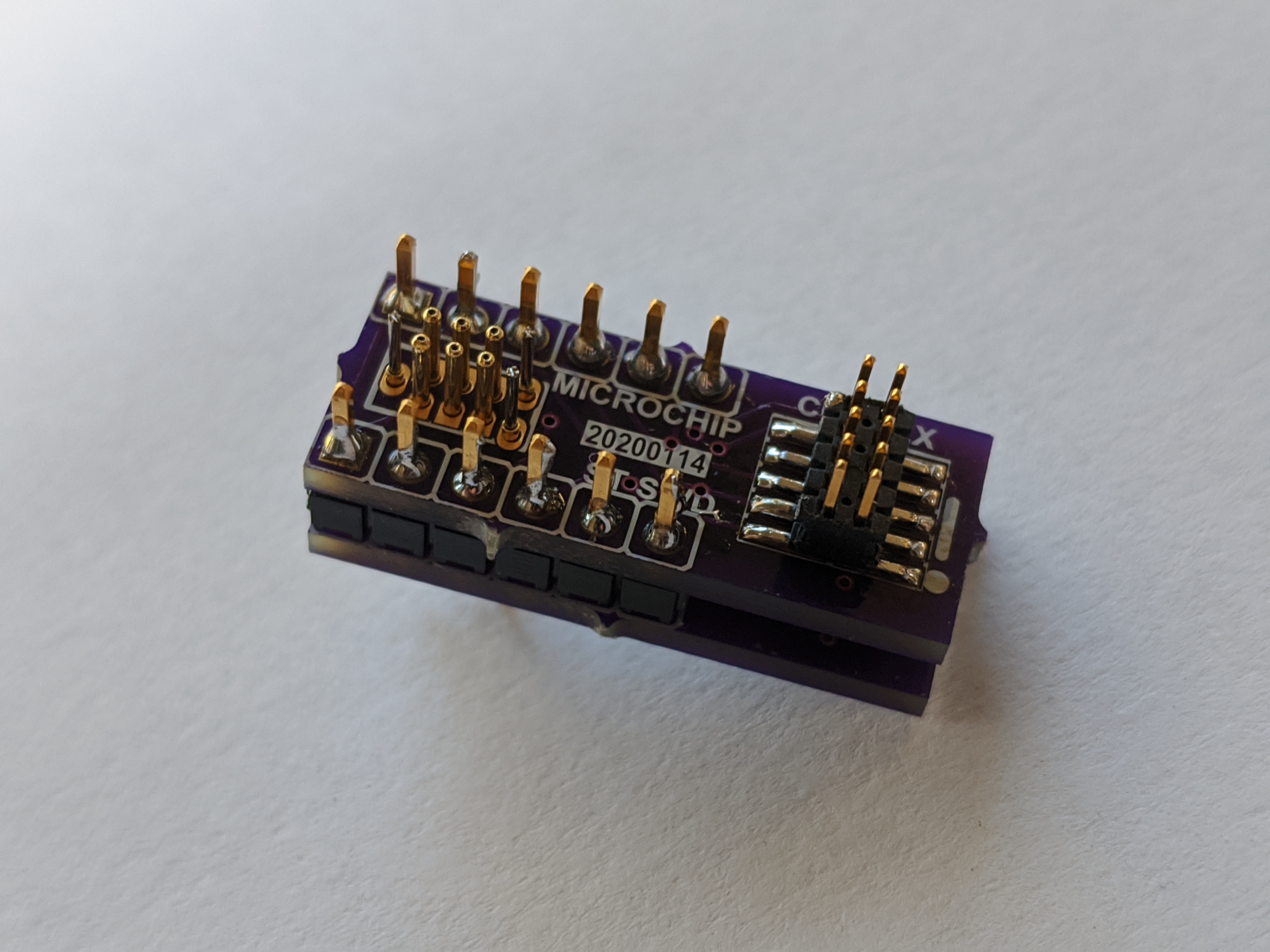
AssemblyTo assemble the design, it is a several step process.
- Using the 100 mil headers solder the two PCBs together.
- Place the PCB on a flat surface.
- Using the six programming pogo pins place the in the PCB and solder them in
- In the three remaining alignment holes, place the pogo pin upside down and solder them in.
- Solder the 50mil pitch Arm Cortex programming connector. Start by soldering just one pin only and getting it aligned, then solder the rest of the pins.
- If there are any solder bridges, carefully clean them up with solder wick.
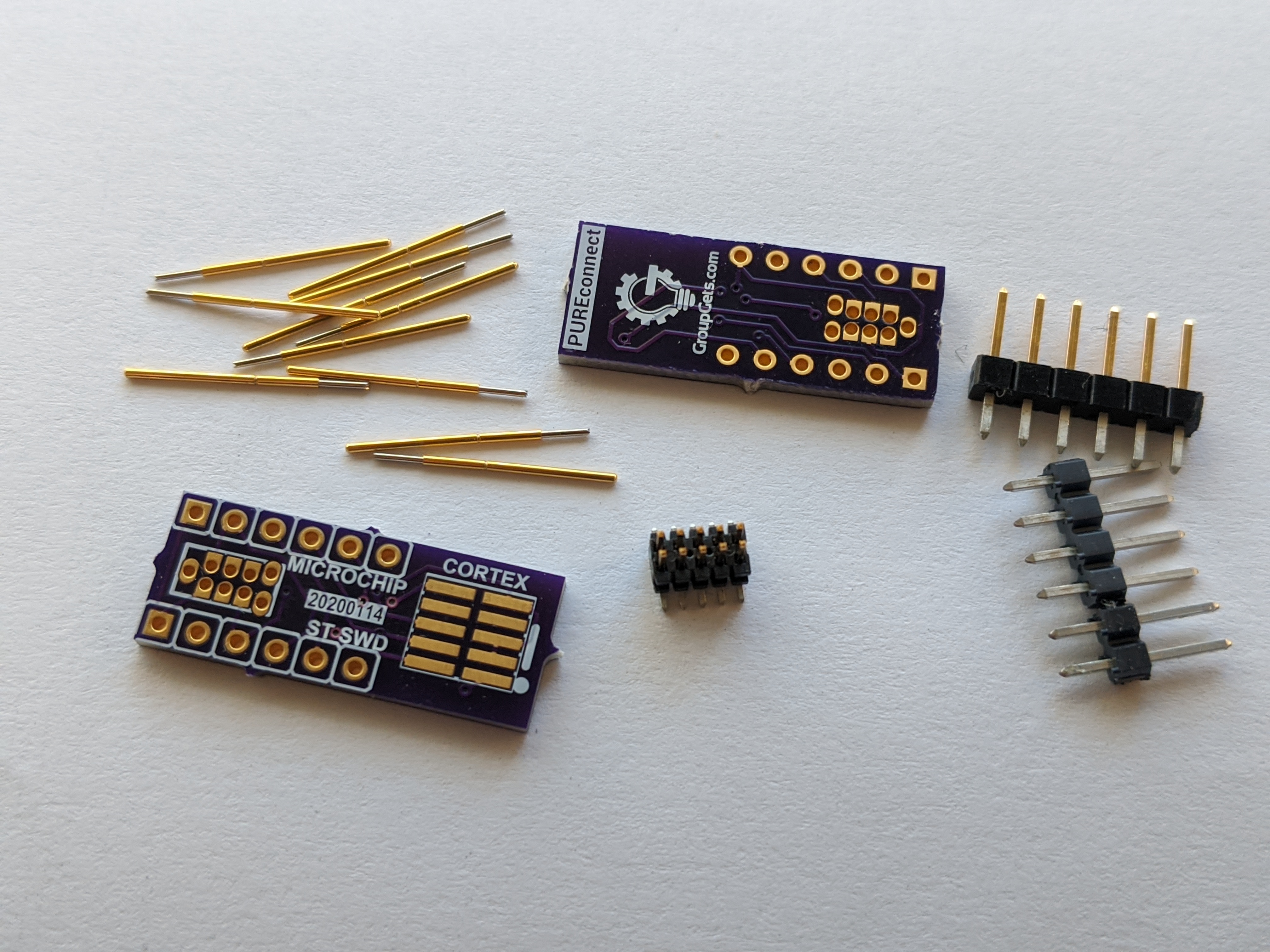
- Two PCBs (the designs are pre-uploaded to OSHPark)
- 1 x 50 mil 2 x 5 SMD male header
- 9 x pogo pins
- 2 x 6 pin 100 mil headers
If anyone wants to make the process simpler, we created a group buy where we have all the parts in kit form. Check it out on GroupGets.com.


Comments