
Hardware components | ||||||
 |
| × | 2 | |||
 |
| × | 2 | |||
 |
| × | 1 | |||
 |
| × | 9 | |||
| × | 15 | ||||
 |
| × | 4 | |||
 |
| × | 1 | |||
 |
| × | 2 | |||
Software apps and online services | ||||||
 |
| |||||
| ||||||
This guide will show you how to send button press data to Adafruit IO from the HUZZAH ESP8266, then use that data to change the color of an LED connected to a second HUZZAH ESP8266.
If you haven't worked your way through the Adafruit IO feed and dashboard basics guides, you should do that before continuing with this guide so you have a basic understanding of Adafruit IO.
You should also go through the setup guide associated with the HUZZAH ESP8266 for use with the Arduino IDE.
If you have completed all of the prerequisites listed above, you are now ready to move on to the Adafruit IO setup steps.
Let's get started!
Adafruit IO SetupThe first thing you will need to do is to login to your Adafruit IO account and get your Adafruit IO Key if you haven't already. Click the AIO KEY button on the right hand side of the window to retrieve your key.
A window will pop up with your Adafruit IO. Keep a copy of this in a safe place. We'll need it later.
Creating the Buttons FeedNext, you will need to create a feed called "Remote Buttons". If you need help getting started with creating feeds on Adafruit IO, check out the Adafruit IO Feed Basics guide.
Next, add a new Gauge block to a new or existing dashboard. Name the block whatever you would like, and give it a max value of 3. Make sure you have selected the Remote Buttons feed as the data source for the gauge.
If you need help getting started with Dashboards on Adafruit IO, check out the Adafruit IO Dashboard Basics guide.
When you are finished editing the form, click Create Block to add the new block to the dashboard.
Next, we will look at how to connect an Arduino via WiFi to Adafruit IO.
Button BoardFirst we will create a simple input controller that will let Adafruit IO know what button was pressed. For this project we will be adding buttons to represent each of the possible states to be passed to our output device.
- 0 will represent "OFF"
- 1 for Red
- 2 for Green
- 3 for Blue
There are a few things we will need to get started:
- 1 x HUZZAH ESP8266
- 3 x colored tactile push buttons (Red, Green, and Blue)
- Six 470 Ohms resistors
- Jumper wires
- Breadboard
Now let's get started with the wiring.
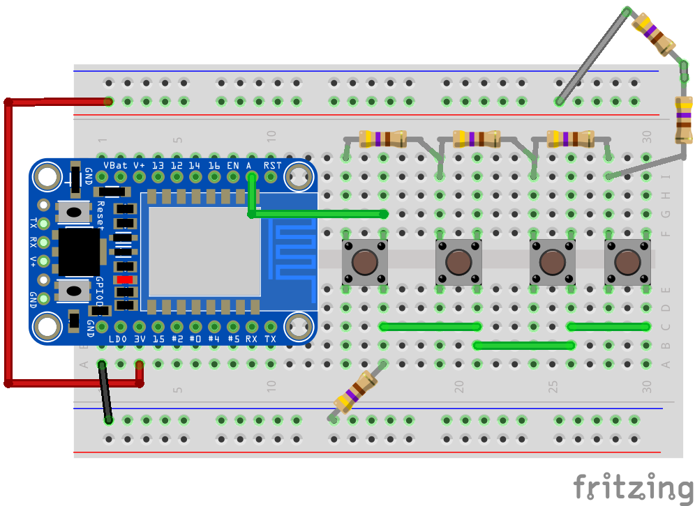
Buttons WiringThere are basically two ways to add simple button input for this project. We could just add a button to each digital pin, but that would limit the number of buttons we could use. This time around we will use resistors along side of our buttons and read the analog value based on what button was pressed. This works by adding one resistor to each button, but also setting the resistors up in series. When nothing is pressed, all of the resistors are used and we get a low number value when the analog pin is read. When we press a button, it shorts out the resistor string and we get another value when the analog pin is read. The higher the button is on the chain, the lower the analog value is. Ultimately, this means that we can add as many buttons as we want and only use up one PIN to do it.
We will now connect all of the components to match what is shown below. There should be just enough room to fit 3 of the colored push buttons and one of the 6MM buttons side by side.
- Connect one of the GND pins to the - side of the breadboard.
- The 3V pin should connect with the side of the breadboard.
- Connect one side of each button to it neighbouring button.
- The last button will connect to the A pin on the HUZZAH.
- Now add one resister connecting GND to the A pin.
- Add the remaining resisters to the other side of each button in series with the last two connecting with the 3V pin.
This can be powered through the FTDI cable, but you may want to add a battery or other power supply by connecting it to the GND and VBat pins.
Now it's time to code.
Buttons CodeArduino DependenciesThis sketch is based off of the ESP8266 examples created by Tony DiCola and Todd Treece. You will need the following Arduino library installed to compile the sketch:
The easiest way to install it is by using the Arduino IDE v.1.6.4+ Library Manager. You will also need to have the ESP8266 board manager package installed. For more info about installing the ESP8266 package, visit the HUZZAH ESP8266 setup guide.
http://arduino.esp8266.com/stable/package_esp8266com_index.json
http://arduino.esp8266.com/stable/package_esp8266com_index.json
Use the package index URL above to get the latest version of the ESP8266 package.
Arduino SketchThe Arduino sketch for this project is fairly straight forward. Copy the following code into a new Arduino sketch. We will need to modify this sketch to include settings for the WiFi connection as well as Adafruit IO credentials.
 /***************************************************
  Must use ESP8266 Arduino from:
    https://github.com/esp8266/Arduino

  Works great with Adafruit's Huzzah ESP board:
  ----> https://www.adafruit.com/product/2471
  Adafruit invests time and resources providing this open source code,
  please support Adafruit and open-source hardware by purchasing
  products from Adafruit!

  Written by Richard Albritton, based on original code by Tony DiCola
  for Adafruit Industries. Adafruit IO example additions by Todd Treece.
  MIT license, all text above must be included in any redistribution
 ****************************************************/
#include <ESP8266WiFi.h>
#include "Adafruit_MQTT.h"
#include "Adafruit_MQTT_Client.h"

/****************************** Pins ******************************************/

#define Buttons       A0  // analog 0

/************************* WiFi Access Point *********************************/

#define WLAN_SSID       "...your SSID..."
#define WLAN_PASS       "...your password..."

/************************* Adafruit.io Setup *********************************/

#define AIO_SERVER      "io.adafruit.com"
#define AIO_SERVERPORT  1883
#define AIO_USERNAME    "...your AIO username..."
#define AIO_KEY         "...your AIO key..."

/************ Global State (you don't need to change this!) ******************/

// Create an ESP8266 WiFiClient class to connect to the MQTT server.
WiFiClient client;

// Store the MQTT server, client ID, username, and password in flash memory.
// This is required for using the Adafruit MQTT library.
const char MQTT_SERVER[] PROGMEM    = AIO_SERVER;
// Set a unique MQTT client ID using the AIO key + the date and time the sketch
// was compiled (so this should be unique across multiple devices for a user,
// alternatively you can manually set this to a GUID or other random value).
const char MQTT_CLIENTID[] PROGMEM  = __TIME__ AIO_USERNAME;
const char MQTT_USERNAME[] PROGMEM  = AIO_USERNAME;
const char MQTT_PASSWORD[] PROGMEM  = AIO_KEY;

// Setup the MQTT client class by passing in the WiFi client and MQTT server and login details.
Adafruit_MQTT_Client mqtt(&client, MQTT_SERVER, AIO_SERVERPORT, MQTT_CLIENTID, MQTT_USERNAME, MQTT_PASSWORD);/****************************** Feeds ***************************************/

// Setup a feed called 'remote-buttons' for publishing changes.
// Notice MQTT paths for AIO follow the form: <username>/feeds/<feedname>
const char RemoteButtons_FEED[] PROGMEM = AIO_USERNAME "/feeds/remote-buttons";
Adafruit_MQTT_Publish RemoteButtons = Adafruit_MQTT_Publish(&mqtt, RemoteButtons_FEED);

/*************************** Sketch Code ************************************/

// remote-buttons state
int ButtonRead = 0;
int current = 0;
int last = -1;

void setup() {

  Serial.begin(115200);

  Serial.println(F("Adafruit IO Example"));

  // Connect to WiFi access point.
  Serial.println(); Serial.println();
  delay(10);
  Serial.print(F("Connecting to "));
  Serial.println(WLAN_SSID);

  WiFi.begin(WLAN_SSID, WLAN_PASS);
  while (WiFi.status() != WL_CONNECTED) {
    delay(500);
    Serial.print(F("."));
  }
  Serial.println();

  Serial.println(F("WiFi connected"));
  Serial.println(F("IP address: "));
  Serial.println(WiFi.localIP());

  // connect to adafruit io
  connect();

}

void loop() {

  // ping adafruit io a few times to make sure we remain connected
  if(! mqtt.ping(3)) {
    // reconnect to adafruit io
    if(! mqtt.connected())
      connect();
    }
    Serial.print("\n");
    Serial.print(analogRead(Buttons));
    ButtonRead = analogRead(Buttons);
    delay(1);
    // grab the current state of the remote-buttons
    if (ButtonRead > 500 && ButtonRead < 600) {
      current = 1;
    }
    if (ButtonRead > 600 && ButtonRead < 750) {
      current = 2;
    }
    if (ButtonRead > 750 && ButtonRead < 900) {
      current = 3;
    }
    if (ButtonRead > 900) {
      current = 0;
    }

  // return if the value hasn't changed
  if(current == last)
    return;

  int32_t value = current;

  // Now we can publish stuff!
  Serial.print(F("\nSending RemoteButtons value: "));
  Serial.print(value);
  Serial.print("... ");

  if (! RemoteButtons.publish(value))
    Serial.println(F("Failed."));
  else
    Serial.println(F("Success!"));

  // save the RemoteButtons state
  last = current;

}

// connect to adafruit io via MQTT
void connect() {

  Serial.print(F("Connecting to Adafruit IO... "));

  int8_t ret;

  while ((ret = mqtt.connect()) != 0) {

    switch (ret) {
      case 1: Serial.println(F("Wrong protocol")); break;
      case 2: Serial.println(F("ID rejected")); break;
      case 3: Serial.println(F("Server unavail")); break;
      case 4: Serial.println(F("Bad user/pass")); break;
      case 5: Serial.println(F("Not authed")); break;
      case 6: Serial.println(F("Failed to subscribe")); break;
      default: Serial.println(F("Connection failed")); break;
    }

    if(ret >= 0)
      mqtt.disconnect();

    Serial.println(F("Retrying connection..."));
    delay(5000);

  }

  Serial.println(F("Adafruit IO Connected!"));

}
The first thing you will need to do is to edit the WiFi connection info at the top of the ESP8266 digital-in sketch. You can use the same connection info you used when you tested your WiFi connection in the HUZZAH ESP8266 setup guide.
#define WLAN_SSID       "...your SSID..."
#define WLAN_PASS       "...your password..."
#define WLAN_SSID       "...your SSID..."
#define WLAN_PASS       "...your password..."
Next, you should replace the Adafruit IO username and key placeholders in the sketch with your username and the key that you retrieved in the Adafruit IO Setup section of this guide.
#define AIO_USERNAME    "...your AIO username..."
#define AIO_KEY         "...your AIO key..."
#define AIO_USERNAME    "...your AIO username..."
#define AIO_KEY         "...your AIO key..."
You will then need to check that the name of your feed matches the feed defined in the sketch.
// Setup a feed called 'remote-buttons' for publishing changes.
// Notice MQTT paths for AIO follow the form: <username>/feeds/<feedname>
const char RemoteButtons_FEED[] PROGMEM = AIO_USERNAME "/feeds/remote-buttons";
Adafruit_MQTT_Publish RemoteButtons = Adafruit_MQTT_Publish(&mqtt, RemoteButtons_FEED);
When you are finished reviewing the sketch and have finished making the necessary config changes, upload the sketch to your HUZZAH using the Arduino IDE. You should also open up your Adafruit IO dashboard so you can monitor the button gauge.
If everything goes as expected, you will see the gauge update on Adafruit IO. You should make sure to open the Arduino IDE's serial monitor if you are having issues with the sketch. It will provide valuable debugging info.
To add more buttons, just copy one of the conditional (if) statements and place it in with the others. Each of the conditional statements represents a button that registers a press if the analog value is within a certain threshold. You will need to set a minimum and maximum threshold for all but the last button. The last button just needs to be grater than the maximum value of the button before it.
 // grab the current state of the remote-buttons
    if (ButtonRead > 500 && ButtonRead < 600) {
      current = 1;
    }
    if (ButtonRead > 600 && ButtonRead < 750) {
      current = 2;
    }
    if (ButtonRead > 750 && ButtonRead < 900) {
      current = 3;
    }
    if (ButtonRead > 900) {
      current = 0;
    }
This sketch is set up to output the analog value of whatever button is pressed. You could figure out was the value of each button is with some math, but it is easier to just look at what the reading is using the serial monitor. Give each button a wide birth to accommodate for any fluctuations.
Don't forget to add a new number to be set as the current value. Also be sure to set the Gauge so that it can accommodate the extra numbers.
Next, we will set up another HUZZAH to output the feed data to an RGB LED.
LEDNow it is time to connect an RGB LED to Adafruit IO so that it can display the color of the button that was pressed.
There are a few things we will need to get started:
- 1 x HUZZAH ESP8266
- 1 x RGB LED
- Jumper wire
- Breadboard
- 3 x 470 ohm resistors (not shown)
Now let's get started with the wiring.
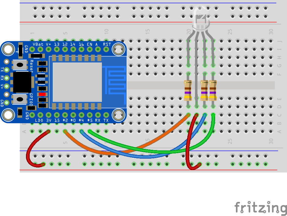
LED WiringWe will now connect all of the components to match what is shown below.
This design uses a Common Anode LRD. You can use a Common Cathode LED, but you will need to change the Arduino code accordingly.
- Connect the 3V pin to the side of the breadboard.
- The longest pin of the LED needs to connect with the 3V pin.
- Pin #2 will connect to the Red pin on the LED.
- The Blue pin should connect with pin #4.
- Connect pin #5 to the Green pin.
This can be powered through the FTDI cable, but you may want to add a battery or other power supply by connecting it to the GND and VBat pins.
Now it's time to code.
LED CodeArduino SketchThe Arduino sketch for this project is fairly straight forward. Copy the following code into a new Arduino sketch. We will need to modify this sketch to include settings for the WiFi connection as well as Adafruit IO credentials.
#include <ESP8266WiFi.h>
#include "Adafruit_MQTT.h"
#include "Adafruit_MQTT_Client.h"

/****************************** Pins ******************************************/

#define Blue            5  // LED Color
#define Green            4  // LED Color
#define Red            2  // LED Color

/************************* WiFi Access Point *********************************/

#define WLAN_SSID       "...your SSID..."
#define WLAN_PASS       "...your password..."

/************************* Adafruit.io Setup *********************************/

#define AIO_SERVER      "io.adafruit.com"
#define AIO_SERVERPORT  1883
#define AIO_USERNAME    "...your AIO username..."
#define AIO_KEY         "...your AIO key..."

/************ Global State (you don't need to change this!) ******************/

// Create an ESP8266 WiFiClient class to connect to the MQTT server.
WiFiClient client;

// Store the MQTT server, client ID, username, and password in flash memory.
// This is required for using the Adafruit MQTT library.
const char MQTT_SERVER[] PROGMEM    = AIO_SERVER;
// Set a unique MQTT client ID using the AIO key + the date and time the sketch
// was compiled (so this should be unique across multiple devices for a user,
// alternatively you can manually set this to a GUID or other random value).
const char MQTT_CLIENTID[] PROGMEM  = __TIME__ AIO_USERNAME;
const char MQTT_USERNAME[] PROGMEM  = AIO_USERNAME;
const char MQTT_PASSWORD[] PROGMEM  = AIO_KEY;

// Setup the MQTT client class by passing in the WiFi client and MQTT server and login details.
Adafruit_MQTT_Client mqtt(&client, MQTT_SERVER, AIO_SERVERPORT, MQTT_CLIENTID, MQTT_USERNAME, MQTT_PASSWORD);

/****************************** Feeds ***************************************/

// Setup a feed called 'lamp' for subscribing to changes.
// Notice MQTT paths for AIO follow the form: <username>/feeds/<feedname>
const char AssistiveCallButtons_FEED[] PROGMEM = AIO_USERNAME "/feeds/assistive-call-buttons";
Adafruit_MQTT_Subscribe AssistiveCallButtons = Adafruit_MQTT_Subscribe(&mqtt, AssistiveCallButtons_FEED);

/*************************** Sketch Code ************************************/

int current = 0;

void setup() {

  // set power switch tail pin as an output
  pinMode(Blue, OUTPUT);
  pinMode(Green, OUTPUT);
  pinMode(Red, OUTPUT);

  digitalWrite(Red, HIGH);
  digitalWrite(Blue, HIGH);
  digitalWrite(Green, HIGH);

  Serial.begin(115200);

  Serial.println(F("Adafruit IO Example"));

  // Connect to WiFi access point.
  Serial.println(); Serial.println();
  delay(10);
  Serial.print(F("Connecting to "));
  Serial.println(WLAN_SSID);

  WiFi.begin(WLAN_SSID, WLAN_PASS);
  while (WiFi.status() != WL_CONNECTED) {
    delay(500);
    Serial.print(F("."));
  }
  Serial.println();

  Serial.println(F("WiFi connected"));
  Serial.println(F("IP address: "));
  Serial.println(WiFi.localIP());

  // listen for events on the lamp feed
  mqtt.subscribe(&AssistiveCallButtons);

  // connect to adafruit io
  connect();
}

void loop() {

  Adafruit_MQTT_Subscribe *subscription;

  // ping adafruit io a few times to make sure we remain connected
  if(! mqtt.ping(3)) {
    // reconnect to adafruit io
    if(! mqtt.connected())
      // listen for events on the lamp feed
     // mqtt.subscribe(&AssistiveCallButtons);

      // connect to adafruit io
      connect();
  }

  // this is our 'wait for incoming subscription packets' busy subloop
  while (subscription = mqtt.readSubscription(1000)) {

    // we only care about the lamp events
    if (subscription == &AssistiveCallButtons) {

      // convert mqtt ascii payload to int
      char *value = (char *)AssistiveCallButtons.lastread;
      Serial.print(F("Received: "));
      Serial.println(value);
      current = atoi(value);
    }
      //Serial.println(current);
  // write the current state to the power switch tail
  // do something different depending on the
  // range value:
  switch (current) {
    case 0:    // your hand is on the sensor
      digitalWrite(Red, HIGH);
      digitalWrite(Blue, HIGH);
      digitalWrite(Green, HIGH);
      break;
    case 1:    // your hand is close to the sensor
      digitalWrite(Red, LOW);
      digitalWrite(Blue, HIGH);
      digitalWrite(Green, HIGH);
      break;
    case 2:    // your hand is a few inches from the sensor
      digitalWrite(Red, HIGH);
      digitalWrite(Blue, HIGH);
      digitalWrite(Green, LOW);
      break;
    case 3:    // your hand is nowhere near the sensor
      digitalWrite(Red, HIGH);
      digitalWrite(Blue, LOW);
      digitalWrite(Green, HIGH);
      break;
  }
  delay(1);        // delay in between reads for stability

  }

}

// connect to adafruit io via MQTT
void connect() {

  Serial.print(F("Connecting to Adafruit IO... "));

  int8_t ret;

  while ((ret = mqtt.connect()) != 0) {

    switch (ret) {
      case 1: Serial.println(F("Wrong protocol")); break;
      case 2: Serial.println(F("ID rejected")); break;
      case 3: Serial.println(F("Server unavail")); break;
      case 4: Serial.println(F("Bad user/pass")); break;
      case 5: Serial.println(F("Not authed")); break;
      case 6: Serial.println(F("Failed to subscribe")); break;
      default: Serial.println(F("Connection failed")); break;
    }

    if(ret >= 0)
      mqtt.disconnect();

    Serial.println(F("Retrying connection..."));
    delay(5000);

  }

  Serial.println(F("Adafruit IO Connected!"));

}
Just like with the Buttons, you will need to do is to edit the WiFi connection info at the top of the ESP8266 digital-in sketch.
#define WLAN_SSID       "...your SSID..."
#define WLAN_PASS       "...your password..."
#define WLAN_SSID       "...your SSID..."
#define WLAN_PASS       "...your password..."
Next, you should replace the Adafruit IO username and key placeholders in the sketch with your username and the key that you retrieved in the Adafruit IO Setup section of this guide.
#define AIO_USERNAME    "...your AIO username..."
#define AIO_KEY         "...your AIO key..."
#define AIO_USERNAME    "...your AIO username..."
#define AIO_KEY         "...your AIO key..."
You will then need to check that the name of your feed matches the feed defined in the sketch.
// Setup a feed called 'remote-buttons' for publishing changes.
// Notice MQTT paths for AIO follow the form: <username>/feeds/<feedname>
const char RemoteButtons_FEED[] PROGMEM = AIO_USERNAME "/feeds/remote-buttons";
Adafruit_MQTT_Publish RemoteButtons = Adafruit_MQTT_Publish(&mqtt, RemoteButtons_FEED);
// Setup a feed called 'remote-buttons' for publishing changes.
// Notice MQTT paths for AIO follow the form: <username>/feeds/<feedname>
const char RemoteButtons_FEED[] PROGMEM = AIO_USERNAME "/feeds/remote-buttons";
Adafruit_MQTT_Publish RemoteButtons = Adafruit_MQTT_Publish(&mqtt, RemoteButtons_FEED);
When you are finished reviewing the sketch and have finished making the necessary config changes, upload the sketch to your HUZZAH using the Arduino IDE. You should also open up your Adafruit IO dashboard so you can monitor the Remote Buttons gauge.
Let's test this thing out now.
Test it OutNow that we have things constructed, power on the Buttons controller as well as the LED boards.
When ever you press one of the buttons on the first Huzzah board, that should change the color of the LED on the second board. So long as they are both connected to the Internet, they can be used together. The status of the buttons that were pressed can also be seen on your Adafruit.IO dashboard.


_3u05Tpwasz.png?auto=compress%2Cformat&w=40&h=40&fit=fillmax&bg=fff&dpr=2)
Comments