In this project, I made an air analyst and alarm system.
This device can currently alert its users if the air quality is bad.
It sounds an alarm when a certain threshold is reached.
This system could be used to monitor hazardous gases in a factory setting. It could help catch leaks before damage is. caused.
It consists of two devices and AWS IoT.
Here is a diagram to explain:
The AVR-IoT board sends data to AWS IoT via MQTT and the ESP32 receives data via MQTT.
Step 1: Setup the AVR-IoT Cellular Mini's SIM card and antenna.Check out this guide from microchip to do this:
AVR-IoT Cellular Mini Overview and hardware preparation
Test it and continue when you can receive sandbox messages(use Google Chrome if you are having trouble)
Step 2: Setup the Arduino IDE for the AVR-IoT Cellular MiniSee this guide for installing DxCore and install the AVR-IoT Cellular library:
AVR-IoT Cellular Mini Starting Guide
Step 3: Setup AWS CLI and AWS IoTThis and Step 4 was probably the most difficult parts in my project.
Setup AWS CLI using a permanent token:
Step 4: Provision the AVR-IoT Cellular board for AWS-IoT:Provisioning for MQTT with AWS Guide
Step 5: Install all Arduino Libraries needed:Install the AVR-IoT Cellular Library if you have not installed it in step 2.
Install the SparkFun ENS160 Arduino library:
SparkFun ENS160 Library Installation Guide
Install the SparkFun BME280 Arduino library:
SparkFun BME280 Library Installation Guide
Step 6: Connect and test the QWIIC sensorsConnect the QWIIC sensors and try running a library example.
Step 7: Upload the main program to the AVR-IoT Cellular MiniDownload this Arduino sketch and upload it to the board, using the upload with programmer button.
Step 8: Prepare a AWS thing for the ESP32Follow this guide until the part in which you upload your main program:
Building an AWS IoT Core Device Using an ESP32.
Ensure to save the secrets and store them properly.
Step 9: Get the AWS device ID from AWSGo to the IoT Core page on AWS.
Click "Things"
You should then see a few devices, one is your ESP32 and one is your AVR-IoT board.
Choose the AVR-IoT board and copy it's name.
Save this name for later.
Step 10: Upload the Alarm program to the ESP32Make sure you have entered all credentials from step 8.
See the below program in the code section, select the tab ESP32.
Change:
// The MQTT topics that this device should publish/subscribe
#define AWS_IOT_PUBLISH_TOPIC "esp32/pub"
#define AWS_IOT_SUBSCRIBE_TOPIC "esp32/sub"
To:
#define AWS_IOT_SUBSCRIBE_TOPIC "[device name of AVR-IoT board]/sensors"Upload the program using Arduino IDE.
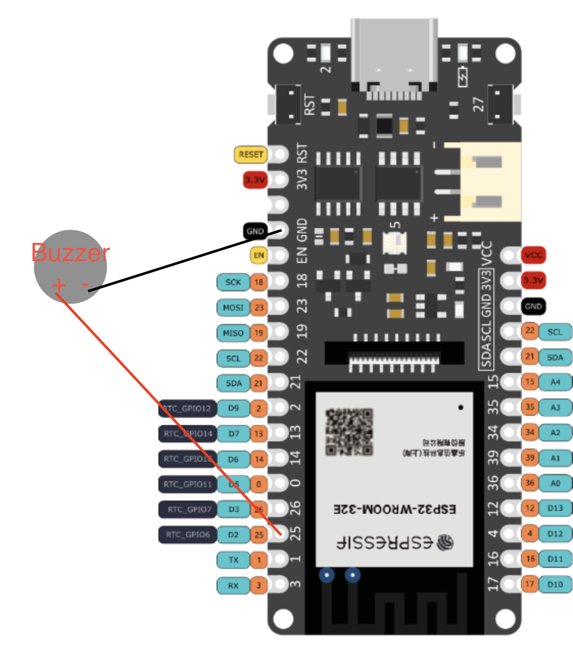
Step 11: Assemble the ESP32 circuit:Locate an appropriate pin for the ESP32's buzzer.
In my case, pin D2 worked for me.
Connect the positive end of the buzzer to pin D2, and connect the negative end to ground.
You will probably need jumper wires and a breadboard for this.
You may want to modify the following code, depending on what pin you used.
tone(D2, 1000);
delay(2000);
noTone();Here are a list of possible improvements:
- Better Low power support
- Better sensors
- Solar power
- LiIon battery
- 3d printed case
- Talkie ESP32, would speak data.
One thing that would be interesting is to have two sets of environmental sensors, one before a filter and one after a filter, to calculate the effectiveness of the filter.
Here is a diagram of the possibility:
Other upgrades that would continue after that upgrade are:
Wind speed and direction monitoring, find where toxic fumes are blowing.
To help with that task, multiple stations would be needed.


_3u05Tpwasz.png?auto=compress%2Cformat&w=40&h=40&fit=fillmax&bg=fff&dpr=2)
Comments
Please log in or sign up to comment.