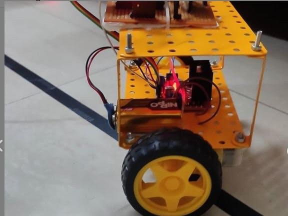
Description : I always wondered how awesome it would be if Robot balances itself on two wheels/legs just like us humans!. Cool isn't it? Yes you are right !! so I decided to build one for myself. So basically this is a self balancing robot that can balance itself on two wheels.
Applications: This Robot has many practical applications in real life.- It can be used in restaurants to serve food to customer just like waiters do today.
- They can also be used in hospitals to carry necessary medical supplies to patients autonomously.
- They can used in houses especially of old people to supply them with necessary needs.
- They can be used in malls for welcoming people entering the malls.
- It is done for obtaining the offset values when the robot is in erect position. The robot is set parallel to ground plane.
- This position of the robot is called balancing position. The set of offset values are then taken such as Ax, Ay, Az and Gx, Gy, Gz (accelerometer and gyroscope reference axis values).These values are kept as reference values.
- Whenever an external disturbing forces comes into play, new set of offset values with respect to reference axis will be formed.
- A feedback mechanism is provided which compares the new set of values with initial reference values. Thus the position of robot from balancing position is determined.
- The angle of tilt can be corrected by controlling dc gear motors/Bo Motors thereby maintaining balance.
PID Conceptfor self balancing Robot:
1. PID stands for :
- P : Proportional
- I : Integral
- D: Derivative
2.Proportional:This is also called as proportional gain and denoted by "Kp".The proportional gain Kp is directly proportional to error. A small change in Kp would automatically be reflected in the error values. Small values of Kp would be insufficient, since the controller might not be able to minimise the error and quickly respond to the changes affecting the system. Large values of Kp cause the system to be unstable and result in weird oscillations.You can look at the image above for the formula of "Kp".
3.Integral: This is also called as integral gain and is denoted by "Ki".The integral gain Ki accounts for the past values of the error and integrates them over time to produce the Ki term. i.e., the integral term lets the controller to take up all the errors that are accumulating over time and creates the next Ki value depending on the previous errors.A larger Ki value results in higher growth of the accumulated error.You can look at the image above for the formula of "Ki".
4.Derivative: This is also called as Derivative gain and is denoted by "Kd"..The derivative gain Kd estimates the future trend of the error based on the current rate of change of error. i.e., it controls the error by analysing the rate of change of error. This helps to dampen the system, thus improving stability. The change in the system will be rapidly evident with smaller change in Ki.You can look at the image above for the formula of "Kd".
5.Error : it is the difference between the desired position and obtained position of the Robot. It is given by:
Error(E) = Desired_Position - Actual_Position- There are many ways by which Kp, Ki and Kd values of the system is tuned one of which is manual tuning through which stability can be easily achieved. Initially the Kp, Ki and Kd values are set to zero. Then Kp value is increased from zero till a point where the system starts to oscillate from its mean position.
- As the Kp value is increased, it was seen that response of the system increase gradually. Keeping the Kp value a constant the Ki value is then increased till a point where it is seen from the system that a small inclination towards a direction tends to accelerate the vehicle towards that direction. When the Kp and Ki values are properly obtained, then the Kd value is increased. The Kd value is increased such that rapid acceleration is reduced considerably.
- Proper KD value results in lesser overshoots and oscillations. After obtaining the rough Kp, Ki and Kd values a fine tuning is done. The above steps are repeated a number of times to obtain the best combination of gain value
- As soon as power is supplied to the Robot the mpu 6050 supplies the values of AX, AY, AZ, GX, GY, GZ to arduino.
- Arduino computes "Kp", "Ki" and "Kd" with the formulas mentioned above and calculates the absolute error between the desired position and position obtained.
- Depending upon the "Error" Robot moves forward or backward which results in balancing of the Robot.
Video:Dont forget to check the Working Video of this awesome Project made by me:)


_3u05Tpwasz.png?auto=compress%2Cformat&w=40&h=40&fit=fillmax&bg=fff&dpr=2)

Comments
Please log in or sign up to comment.