Hardware components | ||||||
_ztBMuBhMHo.jpg?auto=compress%2Cformat&w=48&h=48&fit=fill&bg=ffffff) |
| × | 1 | |||
| × | 1 | ||||
| × | 1 | ||||
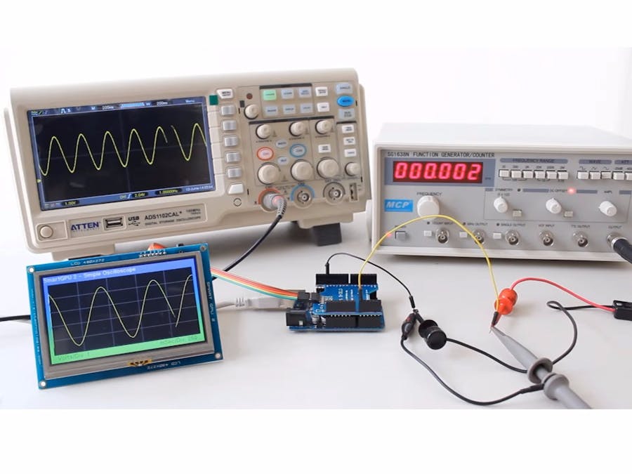
Using an Arduino and a smartGPU2 4.3" we created a touchscreen oscilloscope, which is perfect when we do not have a professional oscilloscope at home, very cheap solution and tons better than debugging with LEDs!
All the source code is ready to compile and load to the Arduino, so the project is 100% ready.
SmartGPU2 + SmartSHIELD + Arduino: Use a simple hook up to connect the smartSHIELD to Arduino, then connect via the 5 pin cable the smartGPU2 to smartSHIELD.
Enjoy!
SmartGPU2 Arduino oscilloscope
C/C++A simple yet functional arduino oscilloscope at a very affordable price!
/*********************************************************
VIZIC TECHNOLOGIES. COPYRIGHT 2014.
THE DATASHEETS, SOFTWARE AND LIBRARIES ARE PROVIDED "AS IS."
VIZIC EXPRESSLY DISCLAIM ANY WARRANTY OF ANY KIND, WHETHER
EXPRESS OR IMPLIED, INCLUDING BUT NOT LIMITED TO, THE IMPLIED
WARRANTIES OF MERCHANTABILITY, FITNESS FOR A PARTICULAR PURPOSE,
OR NONINFRINGEMENT. IN NO EVENT SHALL VIZIC BE LIABLE FOR
ANY INCIDENTAL, SPECIAL, INDIRECT OR CONSEQUENTIAL DAMAGES,
LOST PROFITS OR LOST DATA, HARM TO YOUR EQUIPMENT, COST OF
PROCUREMENT OF SUBSTITUTE GOODS, TECHNOLOGY OR SERVICES,
ANY CLAIMS BY THIRD PARTIES (INCLUDING BUT NOT LIMITED TO
ANY DEFENCE THEREOF), ANY CLAIMS FOR INDEMNITY OR CONTRIBUTION,
OR OTHER SIMILAR COSTS.
*********************************************************/

/********************************************************
 IMPORTANT : This Example is created for the Arduino 1.0 Software IDE
 -------------MINIMUM INPUT VOLTAGE IS 0 VOLTS--------------------
--------------MAX INPUT VOLTAGE IS 3.3 VOLTS----------------------
********************************************************/

#include <SMARTGPU2.h>                     //include the SMARTGPU2 library!

SMARTGPU2 lcd;                             //create our object called LCD

#define GRAY 0x528A                        //GRAY colour of the grid

//OSCILLOSCOPE DEFINES
#define WIN_HORIZONTAL_START 10            //start pixel for the horizontal window
#define WIN_VERTICAL_START   25            //start pixel for the vertical window
#define WIN_HORIZONTAL_END  LCD_WIDTH-10   //size in pixels of the vertical window
#define WIN_VERTICAL_END    LCD_HEIGHT-25  //size in pixels of the vertical window

#define PROBE_INPUT         A0             //select the input pin for the oscilloscope - A0 analog pin
#define MAX_INPUT_VOLTAGE   3.3            //maximum input voltage to the PROBE_INPUT pin
#define MAX_SAMPLES         WIN_HORIZONTAL_END - WIN_HORIZONTAL_START  //must be the substraction of those 2 numbers

#define NUMBEROFVOLTSVALUES       6
#define NUMBEROFMILLISECVALUES    6
const float         voltsPerDivValues[NUMBEROFVOLTSVALUES]           = {0.1, 0.25, 0.5, 1.0, 1.5, 2.0};
const unsigned long millisecondsPerDivValues[NUMBEROFMILLISECVALUES] = {10, 50, 100, 250, 500, 1000};
unsigned char       voltsPerDivPointer=3, millisecondsPerDivPointer=3; //default start values 1voltPerDiv and 250mSecPerDiv

unsigned int sampleBuffer[MAX_SAMPLES];                                //array to store ADC probe samples

/*********************************************************/
void initSampleBuffer(void){
  unsigned int i;
  for(i=0; i < MAX_SAMPLES; i++) sampleBuffer[i] = WIN_VERTICAL_END;
  sampleBuffer[0]= getScaledSample();  //get first sample
}

/*********************************************************/
void showIntro(void){
  int aux=5,xs,ys,i, time=50;

  lcd.setTextSize(FONT4);
  lcd.string(2,2,MAX_X_LANDSCAPE,MAX_Y_LANDSCAPE,"SmartGPU 2 : Simple Oscilloscope", 0);
  lcd.setTextSize(FONT2);
  lcd.string(20,MAX_Y_LANDSCAPE-35,MAX_X_LANDSCAPE,MAX_Y_LANDSCAPE,"Vizic Technologies 2014(c)", 0);
  while(time--){
    //draw next circle
    xs=(sin(((aux*24)*3.14)/180)) * 40;
    ys=(cos(((aux*24)*3.14)/180)) * 40;
    lcd.drawCircle((LCD_WIDTH/2)+xs,(LCD_HEIGHT/2)-ys,2,BLUE,FILL);
    //erase previous circle
    xs=(sin((((aux-5)*24)*3.14)/180)) * 40;
    ys=(cos((((aux-5)*24)*3.14)/180)) * 40;
    lcd.drawCircle((LCD_WIDTH/2)+xs,(LCD_HEIGHT/2)-ys,3,BLACK,FILL);
    //increase vaiable aux
    if(aux++ > 13) aux=0;
    delay(100);
  }
  lcd.erase();               //erase screen before exit
}

/*********************************************************/
void wait_milliseconds_and_process_touch(void){ //wait the millisecondsPerDivValues[] parameter and process touch in the while
  POINT point;

  TCNT1=0;               //reset timer counter - timer counts one step every 4 microseconds
  while(TCNT1 < ((millisecondsPerDivValues[millisecondsPerDivPointer]*(1000/4)) / ((MAX_SAMPLES)/5))){    //wait to reach scaled time
    if((lcd.touchScreen(&point)==VALID) && (point.y > WIN_VERTICAL_END)){    //if a touch is received and if touch on volts per div or in mSec per div strings
      if(point.x < (LCD_WIDTH/2)){        //if touch on volts per div(left half of the screen)
        if(++voltsPerDivPointer >= NUMBEROFVOLTSVALUES) voltsPerDivPointer = 0;
      }else{                              //touch on mSec per div(right half of the screen)
        if(++millisecondsPerDivPointer >= NUMBEROFMILLISECVALUES) millisecondsPerDivPointer = 0;
      }
      lcd.drawRectangle(0,MAX_Y_LANDSCAPE-20,MAX_X_LANDSCAPE,MAX_Y_LANDSCAPE,GREEN,FILL);  //erase previous strings
      lcd.string(20,MAX_Y_LANDSCAPE-20,MAX_X_LANDSCAPE,MAX_Y_LANDSCAPE,"Volts/Div:",0);
      lcd.printNumber(110,MAX_Y_LANDSCAPE-20,voltsPerDivValues[voltsPerDivPointer]);
      lcd.string(MAX_X_LANDSCAPE-140,MAX_Y_LANDSCAPE-20,MAX_X_LANDSCAPE,MAX_Y_LANDSCAPE,"mSec/Div:",0);
      lcd.printNumber(MAX_X_LANDSCAPE-50,MAX_Y_LANDSCAPE-20,millisecondsPerDivValues[millisecondsPerDivPointer]);
      delay(250);
    }
  }
}

/*********************************************************/
unsigned int getScaledSample(void){                        //get a sample and return a value scaled into window vertical size
  float value;
  value = analogRead(PROBE_INPUT);                         //Take a sample from the PROBE
  value = value * MAX_INPUT_VOLTAGE;                       //scale to max input voltage
  value = value / 1023;                                    //divide by the max input value of ADC
  value = value * ((WIN_VERTICAL_END - WIN_VERTICAL_START) / 5); //multiply value by the grid division value in pixels
  value = value / voltsPerDivValues[voltsPerDivPointer];   //finally divide the value by the volts per division parameter
  if(value > (WIN_VERTICAL_END - WIN_VERTICAL_START)) return WIN_VERTICAL_START;
  return WIN_VERTICAL_END - value;                         //return window vertical end substracting the scaled value
}

/*********************************************************/
void drawGrid(){
 unsigned int i;
 for(i=WIN_HORIZONTAL_START; i<=WIN_HORIZONTAL_END; i+=(WIN_HORIZONTAL_END - WIN_HORIZONTAL_START)/5)
   lcd.drawLine(i,WIN_VERTICAL_START,i,WIN_VERTICAL_END,GRAY);
 for(i=WIN_VERTICAL_START; i<=WIN_VERTICAL_END; i+=(WIN_VERTICAL_END - WIN_VERTICAL_START)/5)
   lcd.drawLine(WIN_HORIZONTAL_START,i,WIN_HORIZONTAL_END,i,GRAY);
}

/*********************************************************/
void updateScreen(void){
  static int drawPointer= 0;
  sampleBuffer[drawPointer+1]= getScaledSample();                                              //store a scaled sample
  lcd.drawLine(drawPointer+WIN_HORIZONTAL_START, sampleBuffer[drawPointer], drawPointer+WIN_HORIZONTAL_START+1, sampleBuffer[drawPointer+1], YELLOW);        //draw fresh sample
  drawPointer++;
  if((drawPointer+2) >= MAX_SAMPLES){
    drawGrid();                                                                              //re-draw Grid
    drawPointer = 0;
  }
  lcd.drawLine(drawPointer+WIN_HORIZONTAL_START+1, sampleBuffer[drawPointer+1], drawPointer+WIN_HORIZONTAL_START+2, sampleBuffer[drawPointer+2], BLACK);         //erase old sample
}

/*********************************************************/
void drawInterface(void){
  lcd.drawGradientRect(0, 0, MAX_X_LANDSCAPE, MAX_Y_LANDSCAPE, BLUE, GREEN, VERTICAL);                              //draw background
  lcd.drawRectangle(WIN_HORIZONTAL_START, WIN_VERTICAL_START, WIN_HORIZONTAL_END, WIN_VERTICAL_END, BLACK, FILL);   //draw plotting area
  drawGrid();
  lcd.setTextSize(FONT1);
  lcd.string(2,2,MAX_X_LANDSCAPE,30,"SmartGPU 2 - Simple Oscilloscope", 0);
  lcd.setTextColour(BLACK);
  lcd.drawRectangle(0,MAX_Y_LANDSCAPE-20,MAX_X_LANDSCAPE,MAX_Y_LANDSCAPE,GREEN,FILL);
  lcd.string(20,MAX_Y_LANDSCAPE-20,MAX_X_LANDSCAPE,MAX_Y_LANDSCAPE,"Volts/Div:",0);
  lcd.printNumber(110,MAX_Y_LANDSCAPE-20,voltsPerDivValues[voltsPerDivPointer]);
  lcd.string(MAX_X_LANDSCAPE-140,MAX_Y_LANDSCAPE-20,MAX_X_LANDSCAPE,MAX_Y_LANDSCAPE,"mSec/Div:",0);
  lcd.printNumber(MAX_X_LANDSCAPE-50,MAX_Y_LANDSCAPE-20,millisecondsPerDivValues[millisecondsPerDivPointer]);
}

/*********************************************************/
/*********************************************************/
void setup() { //initial setup
  //Those two functions must always be called for SMARTGPU2 support
  lcd.init();  //configure the serial and pinout of arduino board for SMARTGPU2 support
  lcd.start(); //initialize the SMARTGPU2 processor

  //oscilloscope configurations
  //set analog reference as EXTERNAL to avoid damage to arduino boards when using smartGPU2 as shield, this is already done in the smartGPU2 library
  //analogReference(EXTERNAL); //which AREF is connected to 3.3V of SmartGPU2 board
  pinMode(PROBE_INPUT, INPUT);

  // Timer/Counter 1 initialization
  // Clock source: System Clock
  // Clock value: 250.000 kHz
  // Mode: Normal top=0xFFFF
  TCCR1A=0x00;
  TCCR1B=0x03;  //timer will increase count one step every 4 microseconds
}

/*********************************************************/
/*********************************************************/
/*********************************************************/
/*********************************************************/
void loop() { //main loop draw random colour, size and fill Ellipses
  lcd.baudChange(BAUD7); //for fast drawing we need a big baudRate

  showIntro();           //a Small intro
  drawInterface();       //draws all the oscilloscope body and interface
  initSampleBuffer();    //initialize the sample Buffer to lowest value possible

  while(1){//forever
    wait_milliseconds_and_process_touch();
    updateScreen();
  }
}
2 projects • 22 followers
Vizic Technologies is an embedded electronics design company that designs, and manufactures high end, quality and Intellectual property processors and modules.


Comments
Please log in or sign up to comment.