WasteSense: A Next-Generation Waste Monitoring System is a cutting-edge technology that uses the Matter protocol to transform waste management in smart home ecosystems. This project seeks to solve the shortcomings of traditional trash management systems by offering real-time monitoring, intelligent alarms, and data-driven insights to improve waste collection procedures.
Why WasteSense?
WasteSense was inspired by the inherent inefficiencies of conventional waste management procedures. Overflowing bins, erratic collection schedules, and inefficient routes all contribute to environmental problems, higher operating expenses, and inconvenience for homeowners. WasteSense aims to disrupt this paradigm by exploiting the Matter protocol's capabilities to provide an intelligent, connected, and sustainable waste management system.
Key features:
1. Smart Bin Technology: WasteSense uses ultrasonic or infrared sensors in smart bins to properly assess garbage levels. These sensors monitor fill levels and provide real-time data for effective trash management.
2. Autonomous Actuation: Sensors collect data, and actuators built in smart bins respond. When a trash container reaches a predefined fill level, the system activates actuators that perform tasks like as warnings, notifications, and even autonomous waste pickup.
3. Seamless Matter Protocol Integration: WasteSense uses the Matter protocol stack on the nRF7002 DK to provide interoperability with a wide range of Matter-enabled devices in smart home ecosystems. This integration promotes cohesive communication and interoperability.
4. User-Friendly Interface: The user interface is a specialized mobile app or web site that allows for real-time waste level monitoring, historical data analytics, and adjustable settings. Users can receive notifications, arrange waste pickups, and participate to environmental initiatives.
5. Cloud-Enabled Data Processing: WasteSense uses cloud platforms to securely store and process waste data. This allows for remote monitoring, data analytics, and predictive modeling to optimize waste management tactics.
6. Security Features: Robust security features are provided using secure communication protocols to protect user data, prevent manipulation, and assure the WasteSense system's integrity.
Project Implementation:
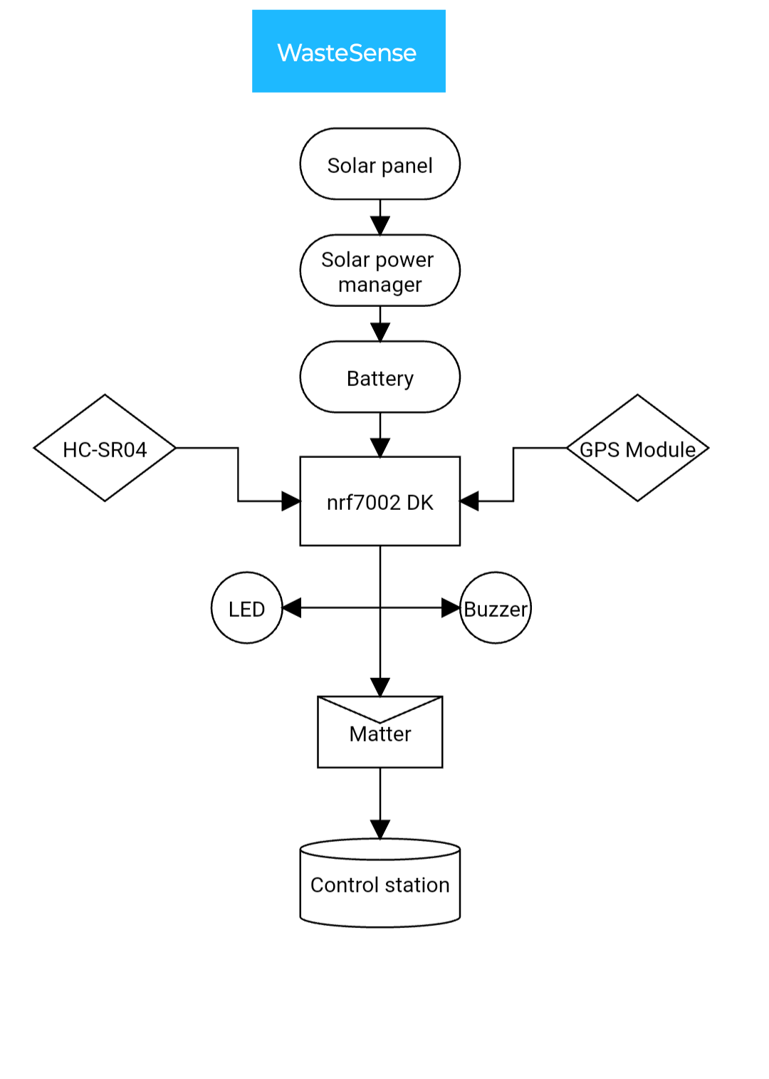
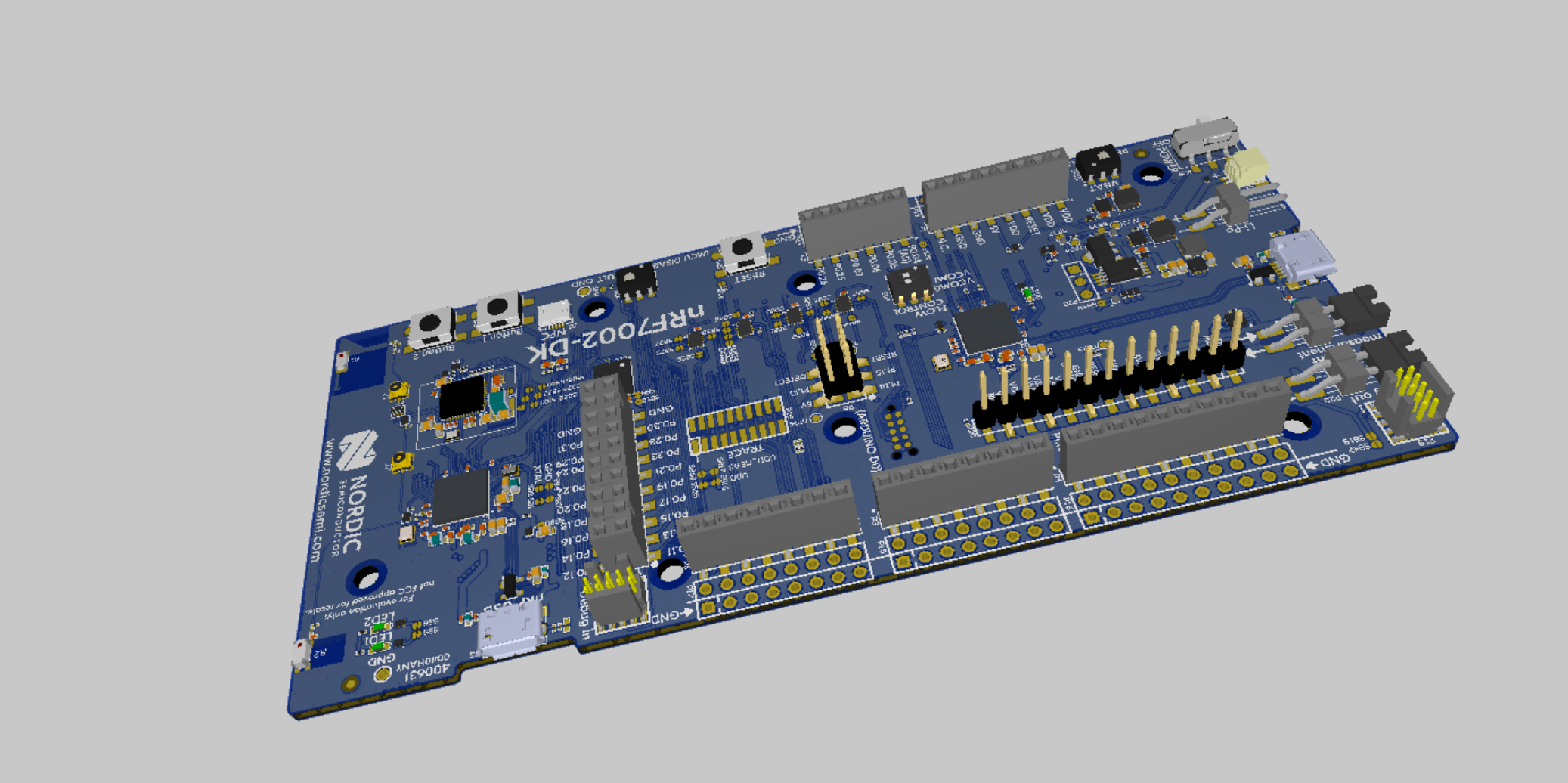
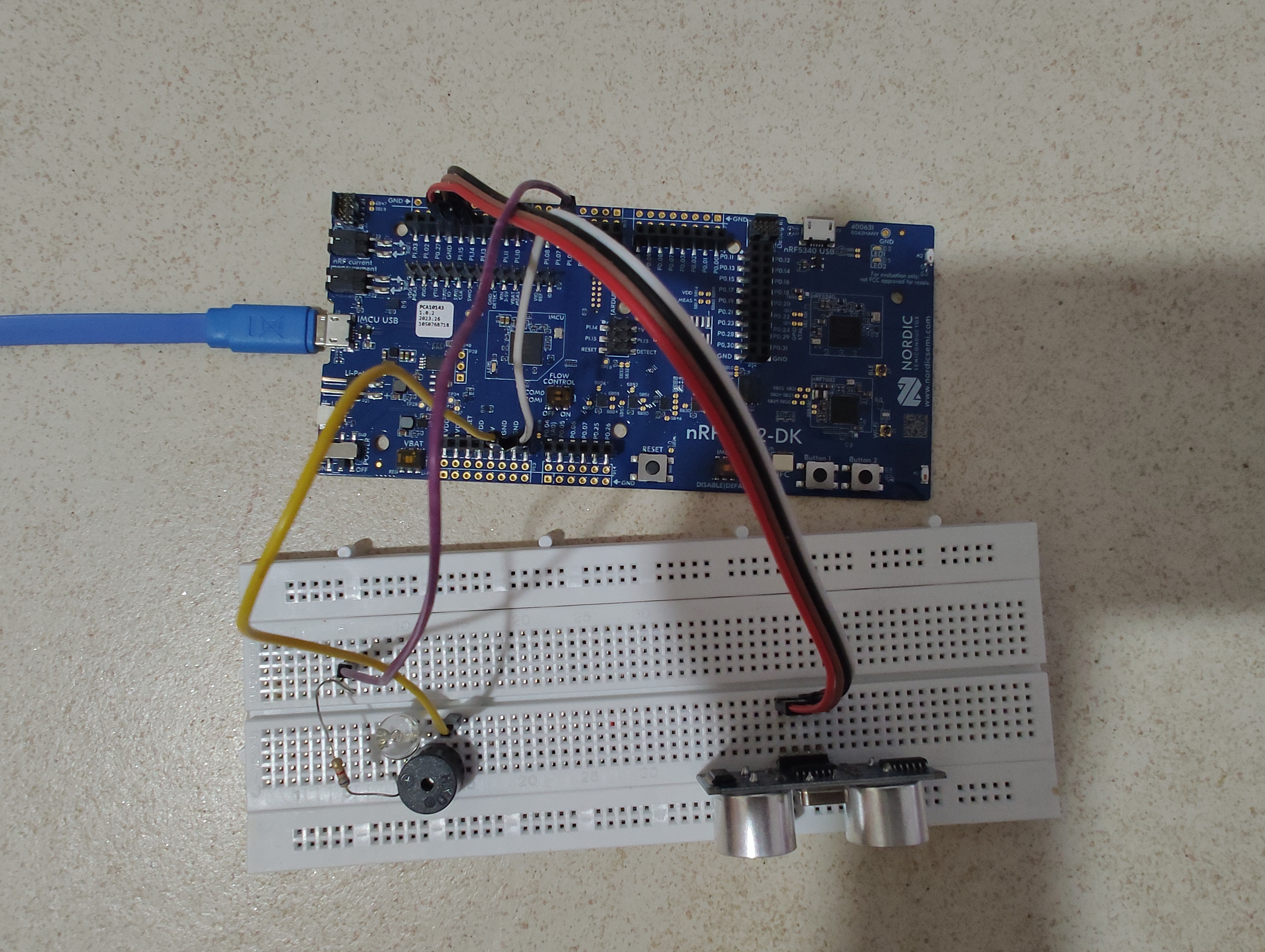
- Hardware Setup: The principal controller is the nRF7002 DK, which implements the Matter protocol stack.
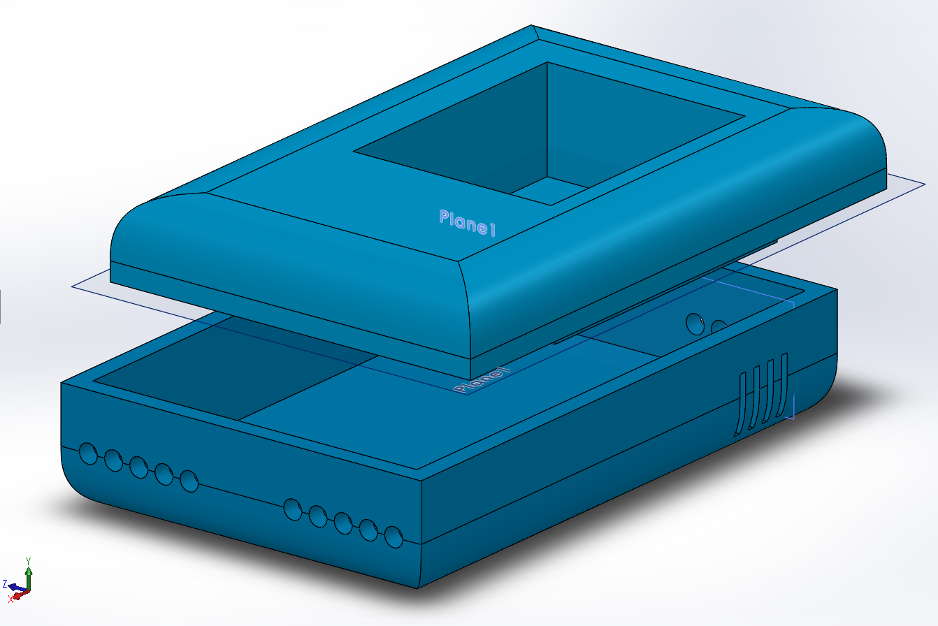
- Smart bins incorporate ultrasonic or infrared sensors to provide accurate garbage level assessments.
- Actuators, such as visual indicators or aural signals, react to fill level information.
- Networking components provide connectivity, while optional add-ons such as cameras and GPS modules improve usefulness.
- Software Implementation:
The nRF7002 DK's embedded firmware manages sensor data, connectivity, and actuators.
- A mobile app or online portal that includes user authentication elements provides users with a full interface.
- Cloud platforms store and process data while also allowing for smooth remote monitoring.
Prerequisites
1. nRF7002 DK
2. Ultrasonic or Infrared Sensors
3. Actuators (LEDs, Buzzers, etc.)
4. Matter Protocol Stack (nRF Connect SDK)
5. Breadboard and Connecting Wires
6. Optional: GPS Module, Camera
Step 1: Setting Up nRF7002 DKNordic Semiconductors has launched the NRF7002, a WiFi companion chip that allows the creation of low-power WiFi6 devices. In this article, we'll walk you through the process of configuring the NRF7002DK board and building a basic application with Nordic's development tools.
Prerequisites:
1. Software installation:
- Visual Studio Code (https://code.visualstudio.com/)
- [nRF Connect for Visual Studio Code Extension Pack](https://marketplace.visualstudio.com/items?itemName=NordicSemiconductor.nrf-connect-for-vscode)
- [nRF Command Line Tools](https://www.nordicsemi.com/Software-and-tools/Development-Tools/nRF-Command-Line-Tools/Download#infotabs) (Version 10.17.3 is suggested).
2. Set the System Path for nrfjprog (Windows):
- Access the system properties window and modify the system environment variables.
- Include the path of nrfjprog (e.g., C:\Program Files\Nordic Semiconductor\nrf-command-line-tools\bin) in the system path.
3. Install nRF Connect for Desktop (version 4.0.0 is recommended):
- [Get nRF Connect for Desktop](https://www.nordicsemi.com/Software-and-tools/Development-Tools/nRF-Connect-for-desktop/Download#infotabs).
- Launch the utility and install the Toolchain Manager to manage the Nordic SDK, Zephyr, and drivers.
4. Download the nRF Connect SDK.
- [Download the newest version].(https://www.nordicsemi.com/Software-and-tools/Software/nRF-Connect-SDK/Download#infotabs)
- When installing, mention the directory (e.g., C:/nordicsemi/).
Board configuration:
Option 1: Install NRF7002 libraries.
1. Transfer the 'nrf7002dk_nrf5340' folder from '\\nrf\boards\arm' to '\\zephyr\boards\arm'.
2. This step ensures compatibility with your projects and grants access to the NRF7002 board configuration.
Option 2: Work with an overlay file.
1. In your application's root directory, create an overlay file named 'nrf7002dk_nrf5340_cpuapp.overlay'.
2. In the overlay file, list the pinout differences between the NRF5340 and NRF7002 boards.
Create your first application.
1. Launch VS Code, select the nRF Extension tab, and click "Create a new application."
2. Choose a template (such as "blinky") and construct the application.
3. Check the board connection in the "Connected devices" section. If not identified automatically, click the reload button.
4. Choose the developed application and click "Add Build Configuration." Select the NRF7002-DK board (nrf7002dk_nrf5340_cpuapp) and activate the debug options.
Flash, run, and debug.
1. Rebuild the app.
2. Flash the application onto the board.
3. Make sure LED0 blinks every 1 second.
Congratulations! You have successfully configured your NRF7002DK board and built a basic application. Consider attending the Nordic Developers Academy's "nRF Connect SDK Fundamentals" course.
Step 2: Configuring nRF Connect SDKIn this phase, we will walk you through the process of configuring the nRF Connect SDK for your Matter project. We'll specifically work on developing a new Matter project with the nRF Connect SDK.
Prerequisites:
Before you begin, make sure the following prerequisites are installed on your development machine:
1. Visual Studio Code: Get and install Visual Studio Code from [https://code.visualstudio.com/].
2. Install nRF Connect for Visual Studio Code Extension Pack. You can get it from the Visual Studio Code Marketplace [here](https://marketplace.visualstudio.com/items?itemName=NordicSemiconductor.nrf-connect-for-vscode).
3. Download and install the nRF Command Line Tools. You may get the tools [here](https://www.nordicsemi.com/Software-and-tools/Development-Tools/nRF-Command-Line-Tools/Download#infotabs). Version 10.17.3 is recommended.
4. Download the nRF Connect SDK. Find the most recent version [here](https://www.nordicsemi.com/Software-and-tools/Software/nRF-Connect-SDK/Download#infotabs). During installation, specify the installation directory (such as C:/nordicsemi/).
Configuring the nRF Connect SDK:
Follow these steps to set up the nRF Connect SDK for your Matter project:
1. Launch Visual Studio Code on your machine.
2. Install nRF Connect SDK Extension: Open the Extensions view ('Ctrl+Shift+X') and search for "nRF Connect."
3. Initialize the nRF Connect SDK:
Open a terminal in Visual Studio Code and enter the following command to initialize the nRF Connect SDK:
West init -m https://github.com/project-chip/connectedhomeip
4. Navigate to Matter Directory: Change working directory to Matter directory in nRF Connect SDK.
cd connectedhomeip
5. Set up a build directory for your Matter project.
West Build -b -p Auto
6. Configure the Build: Run CMake to configure the build.
CMake -GNinja -DBOARD=.
7. Build the project:
Build your Matter project with the following command:
ninja
8. Flash the compiled binary to the nRF7002 DK device.
West Flash
Congratulations! You've successfully configured the nRF Connect SDK for your Matter project. You can move on to the next steps, such as incorporating sensors and actuators, to continue developing your WasteSense application.
Step 3: Implementing Matter ProtocolMatter, an open-source networking standard for the Internet of Things (IoT), promotes interoperability across smart home devices. In this article, we will walk you through the steps of starting a Matter project on the nRF7002 DK with the CHIP (Connected Home over IP) Certificate Tool.
Prerequisites
Before getting started, make sure you have the following prerequisites:
To get started, you'll need the nRF7002 DK development kit, the nRF Connect SDK, a cloned CHIP repository, and knowledge of the CHIP Certificate Tool.
1. Build the CHIP stack.
Start by going to the 'nrf' directory in the CHIP repository:
Cd /examples/nrf.
Generate the Ninja build files and compile the CHIP stack.
./scripts/activate.sh gn gen out/nrf ninja -C output/nrf
2. Create the CHIP Matter Device Example.
Navigate to the Matter Device Example directory:
cd /examples/platform/nrfconnect.
Create the Ninja build files and construct the Matter device example.
... /scripts/activate.sh west build -b nrf7002dk_nrf52840 matter west flash
3. Create Certificates with the CHIP Certificate Tool.
Build the CHIP Certificate Tool:
./scripts/activate.sh gn generate out/host ninja -C out/host chip-cert
Create operational certificates for Matter with the CHIP Certificate Tool. For example:
./out/host/chip-cert gen-cert --type n --subject-chip-id DEDEDEDE0000001E --subject-fab-id FAB000000000001D --valid-from "2020-10-15 14:23:43" --lifecycle 7305: --ca-key /Root-CA-Key.pem --ca-cert /Root-CA-Cert.pem --outkey Chip-Node-Key.chip-b64 -OUT Chip-Node-Cert.chip-b64 --output-format chip-b64
4. Validate certificates.
Use the CHIP Certificate Tool to validate the produced Node certificate.
./out/host/chip-cert validate-cert. Chip-Node-Cert.chip-b64 -C /Chip-ICA-Cert.pem -T /Chip-Root-Cert.pem
5. Example of Flashing and Running the Matter Device
After creating and validating the certificates, flash the nRF7002 DK with the Matter device example:
West Flash
6. Investigate Matter Device.
Connect to the serial console to view the Matter device logs.
nrfjprog -F nrf52 --reset
nrfjprog -f nrf52 --reset—run
You should see Matter device logs showing a successful initialization.
Step 4: Integrating SensorsIn this phase, we'll walk you through attaching ultrasonic or infrared sensors to the nRF7002 DK and integrating sensor drivers into your Matter project using the SDK's sensor libraries.
Prerequisites:
Before you begin, ensure that you have done the preceding stages, which include installing the nRF Connect SDK and establishing your Matter project.
Connecting Sensors:
1. Identify Sensor Pins: Find the pinout for your ultrasonic sensor. These sensors typically feature 4 pins: power (VCC), ground (GND), trigger() and echo.
2. Connect Power and Ground: Connect the sensor's VCC pin to the nRF7002 DK's power source (e.g.5V), and the GND pin to the board's ground pin.
3. Connect Signal Pin: Connect the sensor's SIG pin to an accessible GPIO pin on the nRF7002 DK. Keep the pin number for future usage in your Matter project.3. Connect Signal Pin: Connect the sensor's SIG pin to an accessible GPIO pin on the nRF7002 DK. Keep the pin number for future usage in your Matter project.3. Connect Signal Pin: Connect the sensor's SIG pin to an accessible GPIO pin on the nRF7002 DK. Keep the pin number for future usage in your Matter project.3. Connect Signal Pin: Connect the sensor's SIG pin to an accessible GPIO pin on the nRF7002 DK. Keep the pin number for future usage in your Matter project.
Implementing sensor drivers:
Let's now use the sensor libraries from the nRF Connect SDK to integrate the sensor into your Matter project.
1. Locate and open the sensor configuration file in your Matter project. This file is frequently called'sensor_config.h'. Open it with a text editor.
2. Define Sensor Pin: In the configuration file, locate the section for sensor configuration. Define the GPIO pin to which you connected your sensor. For example:
#define ULTRASONIC_SENSOR_PIN 15 // Replace with the actual pin number.
3. Add Sensor Library: Open your Matter project's main source file (e.g., 'wastesense.c') and include the sensor library at the beginning.
#include // Replace the real library name.
4. Initialize Sensor: In the initialization portion of your code, set the sensor to the configured pin.
// Initialize the ultrasonic sensor: sensor_init(ULTRASONIC_SENSOR_PIN);
5. Periodically read sensor data. This can be done within your main loop:
while (1) { // Get sensor data int distance = sensor_read();
// Process sensor data to operate actuators.
k_sleep(K_MSEC(500)); // Customize sleep time based on application needs.
6. Build and Flash: Build your project and flash the compiled binary to your nRF7002 DK using the previous instructional procedures.
Congratulations! You have successfully integrated sensors into your Matter project. The next step is to install actuators that will control the system based on sensor data.
Step 5: Adding ActuatorsIn this phase, we'll show you how to connect LEDs or buzzers as actuators to the nRF7002 DK and create actuator control logic in your Matter project using the nRF Connect SDK.
Prerequisites:
Check that you have successfully performed the preceding stages, which include installing the nRF Connect SDK, configuring your Matter project, and integrating sensors.
Connecting actuators:
1. Identify Actuator Pins: Determine the pinout of your LED or buzzer. These components usually have a positive (anode) and a negative (cathode) lead. If you are utilizing an LED, the longer the lead, the better.
2. Connect power and ground: Connect the LED or buzzer's positive line to an accessible GPIO pin on the nRF7002 DK. Connect the negative lead to the board's ground pin (GND).
3. Resistors for LEDs: Connect a current-limiting resistor in series with the LEDs. This prevents overcurrent flow and subsequent damage. Connect one end of the resistor to the GPIO pin, and the other to the LED's positive lead.
Developing Actuator Control Logic:
Now, use the nRF Connect SDK to add the actuators into your Matter project.
1. Locate and open the actuator configuration file in your Matter project. This file is frequently called 'actuator_config.h'. Open it with a text editor.
2. Define Actuator Pin: In the configuration file, locate the section for actuator configuration. Define the GPIO pin to which you connected your actuator. For example:
#define LED_ACTUATOR_PIN 16 // Replace with the actual pin number.
3. Add Actuator Library: Open your Matter project's main source file (e.g., 'wastesense.c') and include the actuator library at the beginning:
#include // Replace the real library name.
4. Initialize Actuator: In the code's initialization section, set the configured pin for the actuator.
// Initialize the LED actuator actuator_init(LED_ACTUATOR_PIN);
5. Control Actuator Using Sensor Data:
In your main loop, control the actuator using sensor data. For example, if the waste level is high, turn on the LED; otherwise, turn it off.
while (1) { // Get sensor data int wasteLevel = sensor_read();
// Use waste level to activate or deactivate LED actuator if (wasteLevel > THRESHOLD) { actuator_turn_on(); } else { actuator_turn_off(); }
k_sleep(K_MSEC(500)); // Customize sleep time based on application needs.
6. Build and Flash: Build your project and flash the compiled binary to your nRF7002 DK using the previous instructional procedures.
Congratulations! You have successfully included actuators into your Matter project. The next phase is to build the Matter communication protocol.
Step 6: Creating User Interface (In development...)- Develop a mobile app or web portal using suitable frameworks.
- Implement features for real-time monitoring, historical data, and user alerts.
- Configure cloud platforms for secure storage and processing of waste data.
- Integrate cloud communication in your Matter project for remote monitoring.
#include "app_task.h"
#include "led_util.h"

#include <hal/nrf_gpio.h>
#include <zephyr.h>

//////////////////////////////////////////
#include <ultrasonic_driver.h>
#define ULTRASONIC_TRIGGER_PIN 32
#define ULTRASONIC_ECHO_PIN 31

#define LED_PIN 13
#define BUZZER_PIN 14
#define THRESHOLD_DISTANCE 30 // Placeholder value, replace with your actual threshold

#define ULTRASONIC_TRIGGER_BUTTON 20
#define ULTRASONIC_TRIGGER_BUTTON_MASK (1U << ULTRASONIC_TRIGGER_BUTTON)
//////////////////////////////////////////

using namespace ::chip;
using namespace ::chip::app;
using namespace ::chip::Credentials;
using namespace ::chip::DeviceLayer;

namespace
{
    UltrasonicDriver ultrasonic(ULTRASONIC_TRIGGER_PIN, ULTRASONIC_ECHO_PIN);
    LEDWidget sAlertLED;
    Buzzer sAlertBuzzer;

    bool sAlertActive = false;
} /* namespace */

CHIP_ERROR AppTask::Init()
{
    /* ... Existing code ... */

    /* Initialize LEDs and Buzzer */
    sAlertLED.Init(LED_PIN);
    sAlertBuzzer.Init(BUZZER_PIN);

    /* ... Existing code ... */
}

void AppTask::UltrasonicSensorEventHandler()
{
    const uint16_t distance = ultrasonic.GetDistance();

    if (distance < THRESHOLD_DISTANCE)
    {
        if (!sAlertActive)
        {
            sAlertActive = true;

            // Trigger alert (LED blinking and buzzer)
            sAlertLED.Blink(500, 500); // Blinking pattern
            sAlertBuzzer.Start(1000);  // Start buzzing with a frequency of 1000 Hz
        }
    }
    else
    {
        if (sAlertActive)
        {
            sAlertActive = false;

            // Clear alert (stop LED and buzzer)
            sAlertLED.Set(false);   // Turn off LED
            sAlertBuzzer.Stop();    // Stop buzzing
        }
    }
}

CHIP_ERROR AppTask::StartApp()
{
    ReturnErrorOnFailure(Init());

    AppEvent event = {};

    while (true)
    {
        k_msgq_get(&sAppEventQueue, &event, K_FOREVER);
        DispatchEvent(event);

        // Add Ultrasonic Sensor event handling
        if (event.Type == AppEventType::UltrasonicSensor)
        {
            UltrasonicSensorEventHandler();
        }
    }

    return CHIP_NO_ERROR;
}

void AppTask::ButtonEventHandler(uint32_t buttonState, uint32_t hasChanged)
{
    AppEvent button_event;
    button_event.Type = AppEventType::Button;

    // ... Existing button handling code ...

    // Add handling for a new button (e.g., ULTRASONIC_TRIGGER_BUTTON)
    if (ULTRASONIC_TRIGGER_BUTTON_MASK & buttonState & hasChanged)
    {
        button_event.ButtonEvent.PinNo = ULTRASONIC_TRIGGER_BUTTON;
        button_event.ButtonEvent.Action =
            static_cast<uint8_t>((ULTRASONIC_TRIGGER_BUTTON_MASK & buttonState) ? AppEventType::ButtonPushed :
                                                                                   AppEventType::ButtonReleased);
        button_event.Handler = UltrasonicTriggerButtonHandler;
        PostEvent(button_event);
    }

    // ... Existing button handling code ...
}

void AppTask::UltrasonicTriggerButtonHandler(const AppEvent &event)
{
    if (event.ButtonEvent.PinNo != ULTRASONIC_TRIGGER_BUTTON)
    {
        return;
    }

    if (event.ButtonEvent.Action == static_cast<uint8_t>(AppEventType::ButtonPushed))
    {
        // Trigger Ultrasonic Sensor event
        AppEvent ultrasonic_event;
        ultrasonic_event.Type = AppEventType::UltrasonicSensor;
        PostEvent(ultrasonic_event);
    }
    // Add other button handling logic if needed
1. Verify sensor and actuator connections.
2. Check Matter protocol configurations.
3. Ensure cloud platform credentials are correctly set.
4. Monitor debugging logs for any error messages.
Potential Enhancements:1. Implement GPS module for location tracking.
2. Integrate a camera for visual waste assessment.
3. Explore energy-efficient sleep modes for extended battery life.
WasteSense is now ready for deployment, offering a robust waste monitoring solution with Matter protocol integration. Continuously iterate and enhance the system based on specific use cases and user feedback.
Conclusion:WasteSense combines innovative technology and the Matter protocol to provide an intelligent and sustainable waste management system. The idea not only addresses current inefficiencies, but it also meshes with the larger goals of smart home ecosystems, helping to create a more connected and environmentally responsible future.
I encountered several challenges while working on the project, experiencing difficulties with the software that prevented me from creating the project as initially planned. Despite these obstacles, I remain committed to resolving the issues and enhancing the project. I will provide updates once all the problems are addressed and the project is successfully upgraded.
Resources


_RDlCQKY1zI.png)
_OzwqYy0oQ4.png)

_t9PF3orMPd.png?auto=compress%2Cformat&w=40&h=40&fit=fillmax&bg=fff&dpr=2)


Comments
Please log in or sign up to comment.