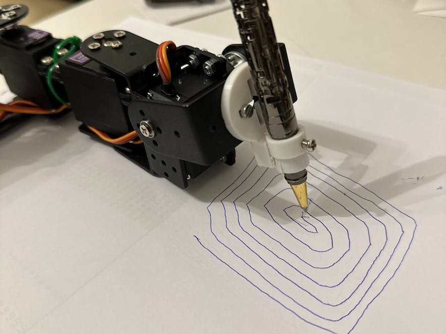
In a world where creativity know no bounds, we have a modern community of artists eager to explore the synergy between human imagination and machines. How about building a tool that could bring their digital drawings to life?
DIY Steps: Building a CollaborativeDrawing Robotic Arm using Blues Notecard, BuesSwan, Servo Motors, and a interactiveUI Canvas.
First, let's understand some fundamentals of Inverse Kinematics.The whole movement of the robotic arm is based on a coordinate system. The drawing area is restricted to a 90x90 mm in this project. This is a square with bottom left at 100, 50 to top right at 190, 140 from the origin of the arm. The drawing area depends on lengths of the links and overall configuration.
We will need Inverse Kinematics for estimating angles of each joint to reach a x, y coordinate. This involves using trigonometry with cosine laws, pythagorean theorem and a lot of patience!
Here's a nice explanation of the concept:
https://robotics-explained.com/inversekinematics
To simulate the behavior here's a nice tool. You can enter the lengths of the links in here and check the angles by moving the end effector in this simulator.
https://www.desmos.com/calculator/wugrira59k
Now, that you have a better idea of how it works, let's start putting things together to make a drawing robot.
Step #1:Let's understand the system architecture from bottom up in the below drawing. I have provided a client UI with a canvas for drawing. When you finish drawing in the canvas, the coordinates of the drawing are captured and sent to a local server. The server contains authentication information for sending the data to the notehub. Notecard is configured for the inbound requests to receive any updates for "data.qi" file. Once the notecard receives the coordinates, Swan reads all the coordinates and performs inverse kinematics and drives the servos.
Step#2:
Test all servo motors and make sure they all are at mid position 90 degrees.
Assemble Servos in the brackets. Below is the top view of the servo when they are at 90 degrees (mid) configuration. Attach the metal horns and the brackets to each other accordingly.
Connect Servos to a powers source and and attach the signal pins to Blues Swan in the following configuration. Do not turn on the power just yet.
Joint_0_Servo => D5
Joint_1_Servo => D9
Jont_2_Servo => D12
Pen_Holder_Servo => D13
Step #4:Clone the repository of the provided code.
If you have access to a 3D printer, print this pen holder and attach it to the end effector. Put a ball pen through it and secure it with screw from the hole provided.
You'll find the stl of this part under "3d_print_files" directory of the repository.
Measure the lengths of all individual links (distance between one servo to another) in mm of your arm. In the Arduino code, you need to update these lengths.
#define L1 104
#define L2 79
#define L3 88
Also, update your Wifi SSD, Password and Product id.
#define WIFI_SSD "SSID"
#define WIFI_PASSWORD "PASSWORD"
#define PRODUCT_ID "PRIDUCT_ID"Now that we have all the hardware in place and mounted everything, it is time to upload the code to Swan. Open the provided code in Arduino IDE.
Add Blues board configuration to the Arduino IDE.
Goto Settings > Preferences
Paste this link to
Additional Boards Manager URLs:
https://github.com/stm32duino/BoardManagerFiles/raw/main/package_stmicroelectronics_index.json
Now, go to Tools > Board > Boards Manager
Search for “STM32”
Install STM32 MCU based boards
Now select Board:
Tools > Board > STM32 boards group > Blues Wireless boards
Select board part number:
Tools > Board part number > Swan R5
Select Upload method:
Tools > Upload method > STM32CubeProgrammer (DFU)
Install STM32Cube as Arduino uses some drivers to upload the code that comes with this software
https://www.st.com/en/development-tools/stm32cubemx.html
Upload the code to the Blues Swan.
Step #7:You'll need some environment variables from the Notehub and enable Programmatic API access
you can follow these instruction to enable it and copy client_id and client_secret.
https://dev.blues.io/api-reference/notehub-api/api-introduction/
Step #8:Node and npm needs to be installed for running the server.
Update the.env file in the server directory with the credentials you generated in the previous step along with Project UID and Device UID.
PORT=3000
CLIENT_ID=your-client-id
CLIENT_SECRET=your-client-secret
PROJECT_UID=your-project-uid
DEVICE_UID=your-device-uid
run the following commands on your terminal
#cd your-path/drawing-robotic-arm/server
#npm install
#npm start
This should start the backend server.
Step #9:Now, let's run the our client UI.
Simply, go to the client directory and open the "client.html" file in your browser.
Clicking in the canvas creates line segments to draw a shape. Double clicking a point ends a shape and starts a new one, allowing you to create multiple disconnected shapes. Drawings are restricted to max 50 points to keep the messages shorter.
Once you finish drawing, you can hit "Execute Drawing" button.
Goto, your Notehub events and check, you should have received a file "data.qi" with the drawing coordinates.
Step #10:Power on all devices and servos. The notecard will now sync with the notehub and pull the "data.qi" file. It will execute the algorithms with Inverse Kinematics and drive the servos for drawing the shapes.
Enjoy your drawing robot companion.


Comments
Please log in or sign up to comment.