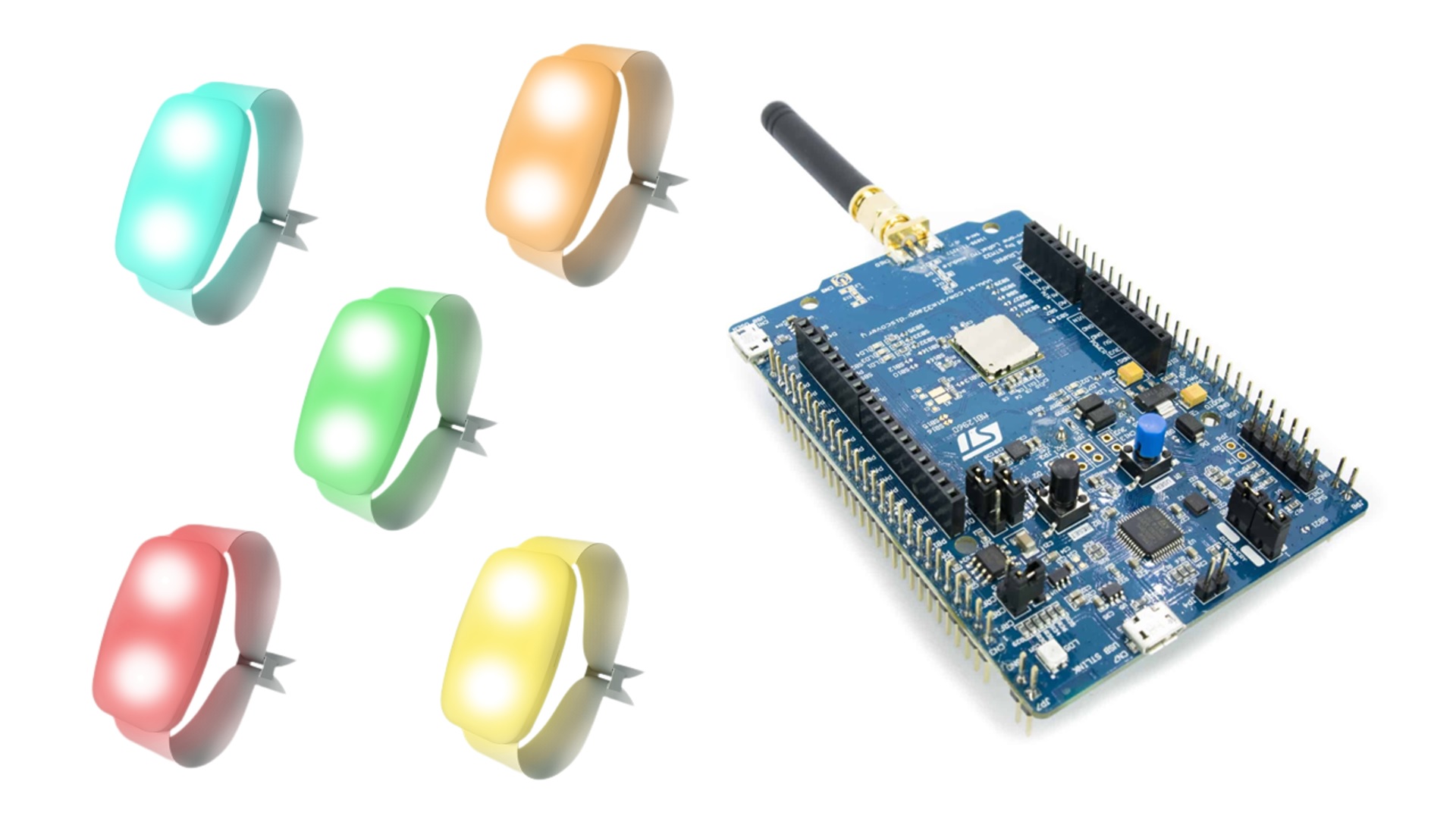
This is not my typical Hackster project. It is in fact as close to collaboration as I got on this platform. I’m so excited because when I work on a project like this it is from couple of years old online posts. This project is so fresh people are still working on it this month! Hopefully, this project will inspire you to go see Tay Tay; if not for the show, at least to get a bracelet, record radio frequency, and contribute to this reverse engineering effort.
It all started when I went to a work conference in Las Vegas. I was not looking forward to the keynotes (a used car salesman giving a B.S. speech full of buzzwords). As I walked into the auditorium, I noticed that each seat has a bracelet with one of two colors. I said to myself “great, free LEDs and batteries”. While trying to tune out the presenter, I managed to open the bracelet and found a PCB with couple of chips on it.
Presentation still going and I’m franticly searching for information about PIXMOB online. Found Daniel Weidman who has the most useful information on PIXMOB RF.
Getting CodesFiles on GitHub have.sub extension which is probably usable with Flipper Zero. Unfortunately, I can’t afford such a device. Looking at RAW_Data I can see a pattern alternating between positive and negative in multiples of 510.
I used Python to get RAW_Data from all pages in edited_rf_captures/915Mhz folder. Next, I converted RAW_Data to Binary then Hexadecimal to make it easier to work with. The codes will be used later in main.cpp. We will need to uncomment the color signals to be sent and update ValidValuesCount.
HardwareI was going to use XIAO RP2040 with CC1101, but ended up using them on a different On–off keying (OOK) project. The B-L072Z-LRWAN1 may not be the easiest board to work with. However, I used it in this project because it required no additional wiring. Anyways, the magic happens in the software. The board I have happened to have a LoRa module on it, but radiolib library should work on many sub-Ghz modules such as RFM69 and CC1101.
The PIXMOB bracelet runs on two 3V batteries, but I've been doing my tests while powering it with 5V.
SoftwareUsed RadioLib Arduino library to send signals to PIXMOB. Found out from the datasheet SPI pins and couple of others to make this library work with this board. Setting transmitDirect will give us the flexablity to send any pattern we want. The 1s and 0s are sent on RADIO_DIO_2_PORT and that's why we need to set it up as output pin.
I usually put the demo at the end of the project. Since this project is ongoing, more observations will follow the demo of what we have working so far. In this video the color needs to alternate between rand_blue_fade and wine_fade_in. wine_fade_in blink consistently, but rand_blue_fade does not, possibly because of synchronization.
- In raw_wild_rf_captures the pattern similar to the one in nothing.sub has been repeated a lot, but it is also followed by 8 zeros (-4000ish microsecods). I think we should add 8 zeros at the end of nothing.sub or -4080 microsecods if we are going to keep 510 microsecods duration.
- Colors in raw_wild_rf_captures appeared to be followed by nothing.sub without preamble (also add 8 zeros at the end as discussed above)
- Out of the edited_rf_captures, only four worked consistently:
gold_fade_in
gold_fast_fade
white_fastfade
wine_fade_in
Here is the binary for these colors:
1010101010101010 0110010100 10000100 10010001 10110101 10000100 10001100 01000101 10000100 10101101 000000
1010101010101010 0101101101 10000100 10010001 10110101 10000100 01001001 01000101 10000100 10001010 000000
1010101010101010 0101011010 10000100 10110101 10110101 10110101 01001001 01000101 10000110 11
1010101010101010 0110100110 10000100 10000100 10110101 10000100 10001100 01000101 10000100 10100001 000000
That leads me to believe that 1 (maximum value) = 10110101 and 0 (minimum value) = 10000100. I concluded that based on three 1 occurrences in white, and one occurrence shifted in red and blue.
- In that pattern we have 16 bit preamble + 10 bits + ‘10000100’ + 3 colors*8 bits + 5 * 8 for speed, fade, effect, etc. Not sure where is CRC or addresses/broadcast.
UPDATE: 6/2/2024
One of the reasons I used B-L072Z-LRWAN1 is to easily add a display later. I also added a buzzer to give the user feedback when touch is successful. Instead of converting binary from the beginning to include the preamble and the extra two bits, I modified the code to focus only on the 9 bytes that change. I added a mini photocell that I got in a college kit back in 2005 (I knew I'll use it one day) to capture which code produced light while brute forcing.
I spent days trying to figure out CRC and finally came across sueppchen's work. For more details see my next project
https://www.hackster.io/abouhatab/controlling-pixmob-waveband-with-wemos-d1-mini-and-cc1101-404c89
https://coda.io/@amrpixmob/rf-for-chamsys


Comments
Please log in or sign up to comment.