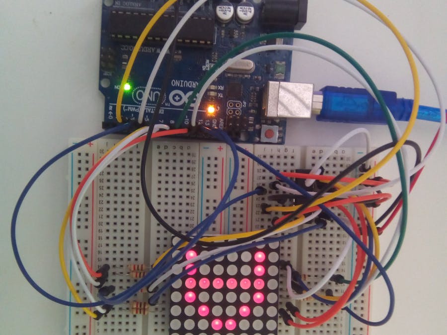
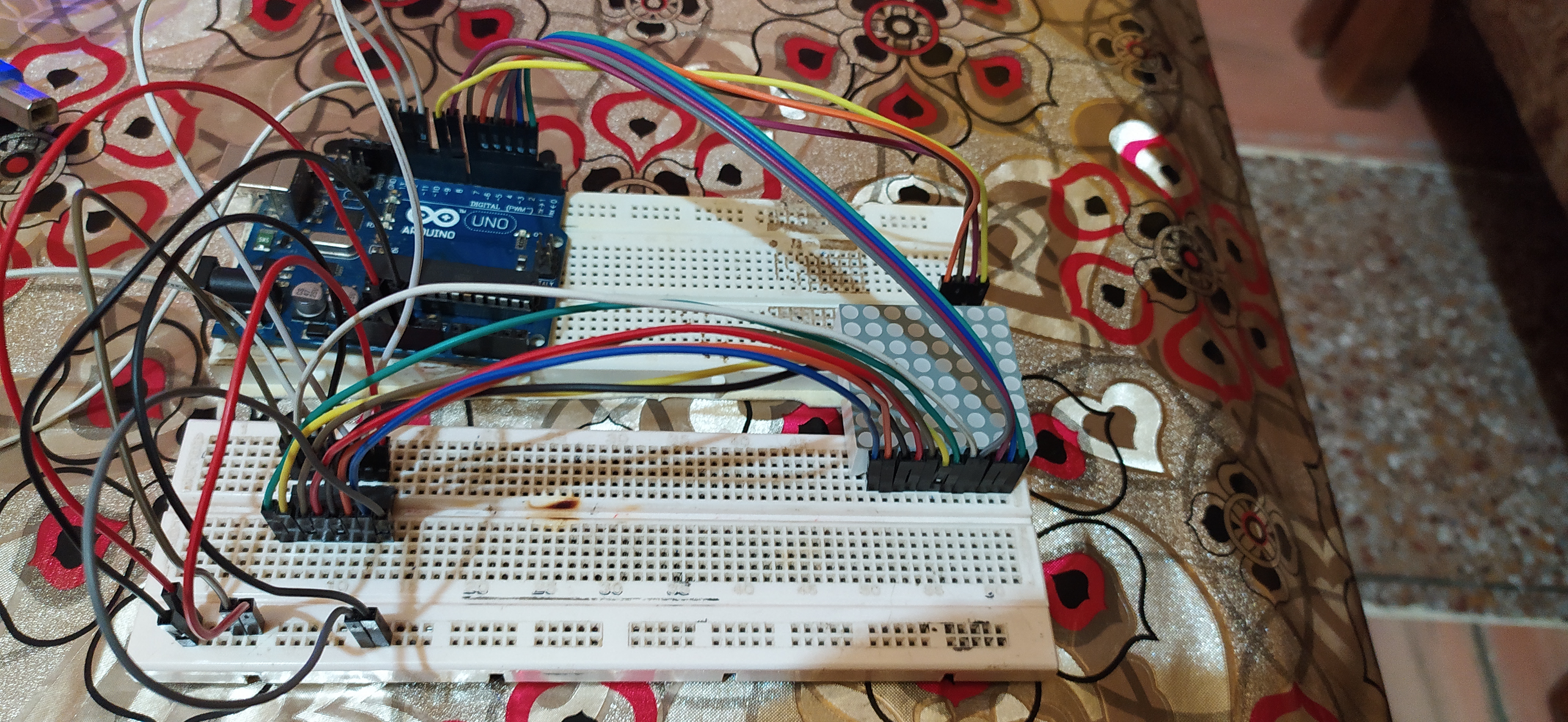
This project uses a 8x8 led matrix to display the direction in which the accelerometer is tilted. The 8x8 led matrix is operated using a SN74HC595N shift register (without the aid of any drives/libraries).
2. Demonstration3. Circuit- 3.1 Components
i. 8x8 led matrix
An 8 x 8 LED matrix display is used in this project to display the information. LED matrices are available in different styles like single color, dual color, multi-color or RGB LED matrix.
ii. Accelerometer sensor
Accelerometer sensors are ICs that measure acceleration, which is the change in speed (velocity) per unit time.Measuring acceleration makes it possible to obtain information such as object inclination and vibration.
iii. 74HC595 shift register
A shift register allows you to expand the number of pins you can use from your Arduino (or any micro controller for that matter) by using what is known as bit-shifting.
- 3.2 Connections
i. For 8x8 led matrix
>>Connect the pins R1 to R8 to the pins 2 to 9 on the Arduino.
>>Connect the pins C1 to C8 to the pins Qa to Qh on the shift register.
ii. For the shift register
>>To start with, connect pins 16 (VCC) and 10 (SRCLR) to the 5V pin on the Arduino and connect pins 8 (GND) and 13 (OE) to the Gnd pin on the Arduino. Pin 13 (OE) is used to enable the outputs, as this is an active low pin we can just connect this directly to ground.
>>Next we need to connect the three pins that we will control the shift register with:
**Pin 11 (SRCLK) of the shift register to pin 11 on the Arduino – this will be referred to as the “clock pin”.
**Pin 11 (SRCLK) of th.e shift register to pin 11 on the Arduino – this will be referred to as the “clock pin”.
**Pin 13 (SER) of the shift register to pin 13 on the Arduino – this will be referred to as the “data pin”.
iii. For accelerometer
>>Connect VCC pin to 5V and Gnd pin to Gnd.
>>Connect x_out pin to A0 on Arduino, y_out pin to A1 on Arduino and z_out pin to A2 on Arduino.
int i,j,t=100,dpin=13,lpin=12,cpin=11;
int r[8]={2,3,4,5,6,7,8,9};               //array of row pin nos.
byte up[8]={B11100111,                   //binary array inputs for the shift register
            B11000011,
            B10000001,
            B00000000,
            B11100111,
            B11100111,
            B11100111,
            B11100111
};
byte down[8]={B11100111,
              B11100111,
              B11100111,
              B11100111,
              B00000000,
              B10000001,
              B11000011,
              B11100111
};
byte left[8]={B11101111,
              B11001111,
              B10001111,
              B00000000,
              B00000000,
              B10001111,
              B11001111,
              B11101111
};
byte right[8]={B11110111,
               B11110011,
               B11110001,
               B00000000,
               B00000000,
               B11110001,
               B11110011,
               B11110111
};
byte ur[8]={B11110000,
            B11111100,
            B11111010,
            B11110110,
            B11101111,
            B11011111,
            B10111111,
            B01111111
};
byte ul[8]={B00001111,
            B00111111,
            B01011111,
            B01101111,
            B11110111,
            B11111011,
            B11111101,
            B11111110
};
byte dr[8]={B01111111,
            B10111111,
            B11011111,
            B11101111,
            B11110110,
            B11111010,
            B11111100,
            B11110000
};
byte dl[8]={B11111110,
            B11111101,
            B11111011,
            B11110111,
            B01101111,
            B01011111,
            B00111111,
            B00001111
};
byte o[8]={B11111111,
           B11111111,
           B11111111,
           B11100111,
           B11100111,
           B11111111,
           B11111111,
           B11111111
};
byte no[8]={B01111110,
            B10111101,
            B11011011,
            B11100111,
            B11100111,
            B11011011,
            B10111101,
            B01111110
};
void setup()
{
  pinMode(dpin,OUTPUT);
  pinMode(lpin,OUTPUT);
  pinMode(cpin,OUTPUT);
  pinMode(a,INPUT);
  pinMode(b,INPUT);
  pinMode(c,INPUT);
  for( i=0;i<8;i++)
  {
    pinMode(r[i],OUTPUT);
    digitalWrite(r[i],LOW);
  }
}
void disp(byte ch[8])
{
  for(i=0;i<8;i++)
  {
    digitalWrite(r[(7-i)],HIGH);
    digitalWrite(lpin,LOW);
    shiftOut(dpin,cpin,MSBFIRST,ch[i]);       //MSBFIRST- Most Significant Bit First
    digitalWrite(lpin,HIGH);

    digitalWrite(lpin,LOW);
    shiftOut(dpin,cpin,MSBFIRST,B11111111);   //to prevent fluttering
    digitalWrite(lpin,HIGH);
    digitalWrite(r[(7-i)],LOW);
  }
}
void loop()
{
  int x,y,z;
  x=438-analogRead(A0);   //correction in the raw values of the sensor to calibrate it
  y=434-analogRead(A1);
  z=514-analogRead(A2);
  if(z<90)
  {
  if(x<-10 && (y>-10 && y<10))
    for(j=0;j<t;j++)
      disp(up);
  else if(x>10 && (y>-10 && y<10))
    for(j=0;j<t;j++)
      disp(down);
  else if(y<-10 && (x>-10 && x<10))
    for(j=0;j<t;j++)
      disp(left);
  else if(y>10 && (x>-10 && x<10))
    for(j=0;j<t;j++)
      disp(right);
  else if(x<-10 && y<-10)
    for(j=0;j<t;j++)
      disp(ul);
  else if(x>10 && y<-10)
    for(j=0;j<t;j++)
      disp(dl);
  else if(x<-10 && y>10)
    for(j=0;j<t;j++)
      disp(ur);
  else if(x>10 && y>10)
    for(j=0;j<t;j++)
      disp(dr);
   else if((x<10 && x>-10)&& (y>-10 && y<10))
    for(j=0;j<t;j++)
      disp(o);
  }
  else
    disp(no);
}
The code is self explanatory as I have added the comments.
- Working principle
>>In the disp() function, we write the row of leds we want to turn on to HIGH. Then we write the Latch pin to LOW as it signifies that the data is about to be sent. The shiftOut() fuction passes the array of bits (the order in which we want to turn the columns on) to the shift register. Then we write the Latch pin to HIGH to send this binary data to the shift register.
>>MSBFIRST signifies that the first bit sent to the shift register will be the leftmost bit of the binary array and the in order of moving towards right through the array.
>>The for loop is used to activate different rows in order to display the whole symbol.


_ztBMuBhMHo.jpg?auto=compress%2Cformat&w=48&h=48&fit=fill&bg=ffffff)


Comments