Commercial Multi-Copter Use Case Challenges
Some interesting commercial applications, in architectural work, civil engineering, plant maintenance and photography involve flying so very close to an inspected object that there is a small risk of a propeller blade hitting the same or another object. Without a very fast response, there can be damage to the object, the propeller, the motor drive mechanisms and motor drive electronics. In large drones with sophisticated cameras and instrumentation, the cost of the drone can easily exceed $8000 to $10,000. We would like to avoid damage to property being inspected and prevent even minor damage to the drone. To achieve these ends, a means of detecting even the slightest brush of the propeller with any object is desired. To do this involves monitoring all of the rotors of a multi-copter. This monitoring creates the ability to rapidly take autonomous action at the very beginning of propeller to object contact. It is anticipated that an autonomous response strategy can be implemented that has a response time much faster than the typical operator reaction time.
Flex IO to the rescue!
Flex IO is used to monitor the velocity of the propellers of the multi-copter in real-time providing the needed real-time feedback for safety, velocity control, and system performance monitoring. This demonstration is a repackaging of a Kinetis SDK based SCI implementation and is developed with Processor Expert and the Kinetis SDK.
Project Accomplishments
14 ROTOR MULTI-COPTER CONSTRUCTED
The construction of the multi-copter was a later addition to the project goals. Since the monitoring aspect of the project required the commanded propeller velocity to be known, it seemed right to implement a velocity control loop. Once the decision to code the velocity control loops was made, then the construction of a multi-copter seemed almost irresistible.
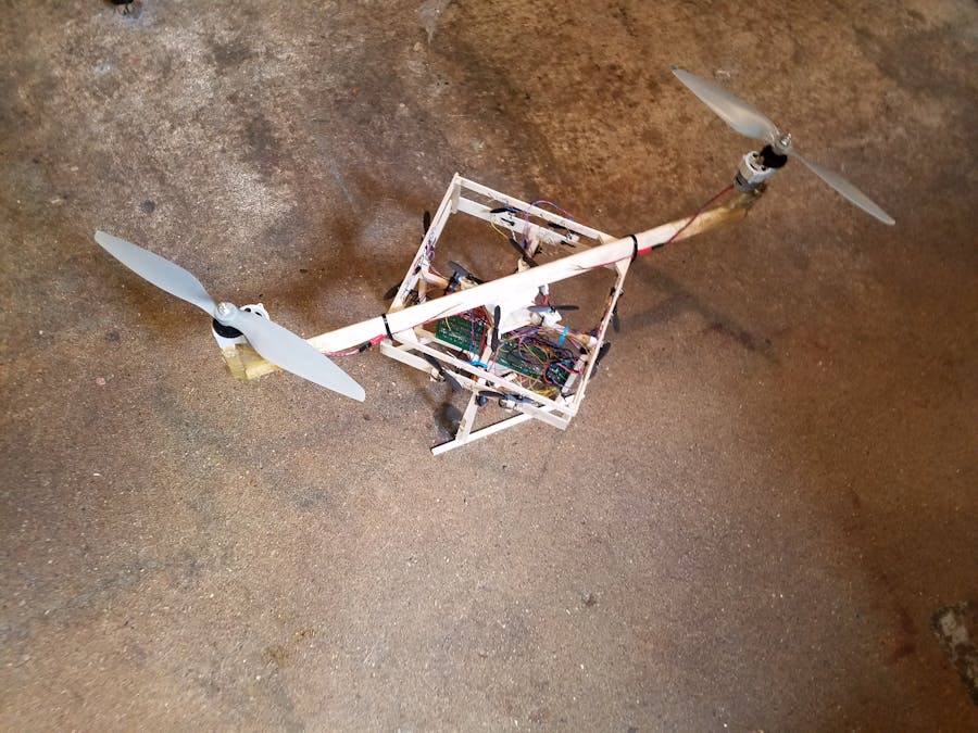
The quickest method was used to construct a 12 rotor multi-copter, using a quad-copter and adding to it an additional framework to hold the FRDM-K82F, 8 DC motors, optical sensors, and additional motor drive and signal conditioning electronics.
The quadcopter does the flight control of the framework. The 8 DC motors of the framework are adjusted to maintain a constant velocity to lift the additional weight of the framework. The variation of the quadcopter rotor velocities maintains the attitude control of the framework.
More sophisticated control schemes will follow in later implementations. A likely scheme will copy the propeller velocities of quad-copter rotors to the nearest pairs of propellers in the added framework. In this way a more maneuverable multi-rotor will result.
Capabilities of the Project Submitted
VELOCITY CONTROL OF 8 ROTORS
A very simple control scheme is used to output PWM signals to Darlington power stages. While the original focus was on brushless motors, I had small brush type DC motors available from two crash kits I had already purchased.
The propeller blade detection can likely be used to estimate the commutation points for brushless motors.
PROPELLER SLOW DOWN DETECTION
A very simple slow down detection is implemented.
The use of Processor Expert and the Kinetis SDK enabled very rapid prototyping this system. The author doubts that the system could be constructed for the May 1st submission NXP FTF contest deadline without using the code generation and resource allocation features of Processor Expert.
Software Environment
Kinetis Design Studio, using KSDK 1.3 with Processor Expert
The Story
Build Considerations
This project really did start simply, as a means to detect bad rotor situations, but people will always ask, “Can it really fly?” So it was irresistible to do a multi-copter build. It is a matter of “putting your money where your mouth is” so I can say “Yes, It can fly!”
It starts with a flashing LED.
I always try to start with the simple but needed pieces first. Printing “Hello World!” on the debug serial output and blinking the Green LED gives us a good feeling. We really need a precise one second interrupt for doing timestamps so this really is important. The debug serial output has proved to be very useful in debugging this application. The project development points will be stored as complete projects on GitHub. In this way, those deeply interested in the Processor Expert or other aspects of the software development can examine any of the development points.
Upon request, a link to a zipped archive will be provided , to easily import the project to Kinetis Design Studio.
What is a timestamp and how does it help with multi-copter control?
The timestamps in the software are in 10 microsecond resolution. The difference in time “delta” timestamps are also in 10 microsecond resolution. The primary goal of the project is to track propeller speed, control propeller speed and make instant notifications of any failure to maintain commanded propeller speed. Optical sensors are used to detect the propeller and the “delta” timestamp measured with each passing propeller blade, and this is the means of achieving the project goals.
The Processor Expert FlexIO SCI RX component
Processor Expert helped provide 8 channels of RX only SCI. In future development, the component will be modified to receive 32 bit data, to improve the application by reducing the frequency of interrupt service events. In the 32 bit mode the “baud” rate will be adjusted so that a one rotation of the blade is tracked with the interrupt routine, rather than this current implementation which tracks half revolutions of the propeller. Further reduction of interrupt service frequency could also be achieved where 2 complete revolutions are tracked per interrupt event. The blade activity in these more advanced implementations can be examined in the 32bit serial data gathered by the FlexIO 32 bit serial data shifter. This will verify that the “baud rate” is set correctly or recommend adjusting the “baud rate”. This process will need to be performed only occasionally, and all of the data need not be examined to adequately track propeller speed.
Detecting the propeller
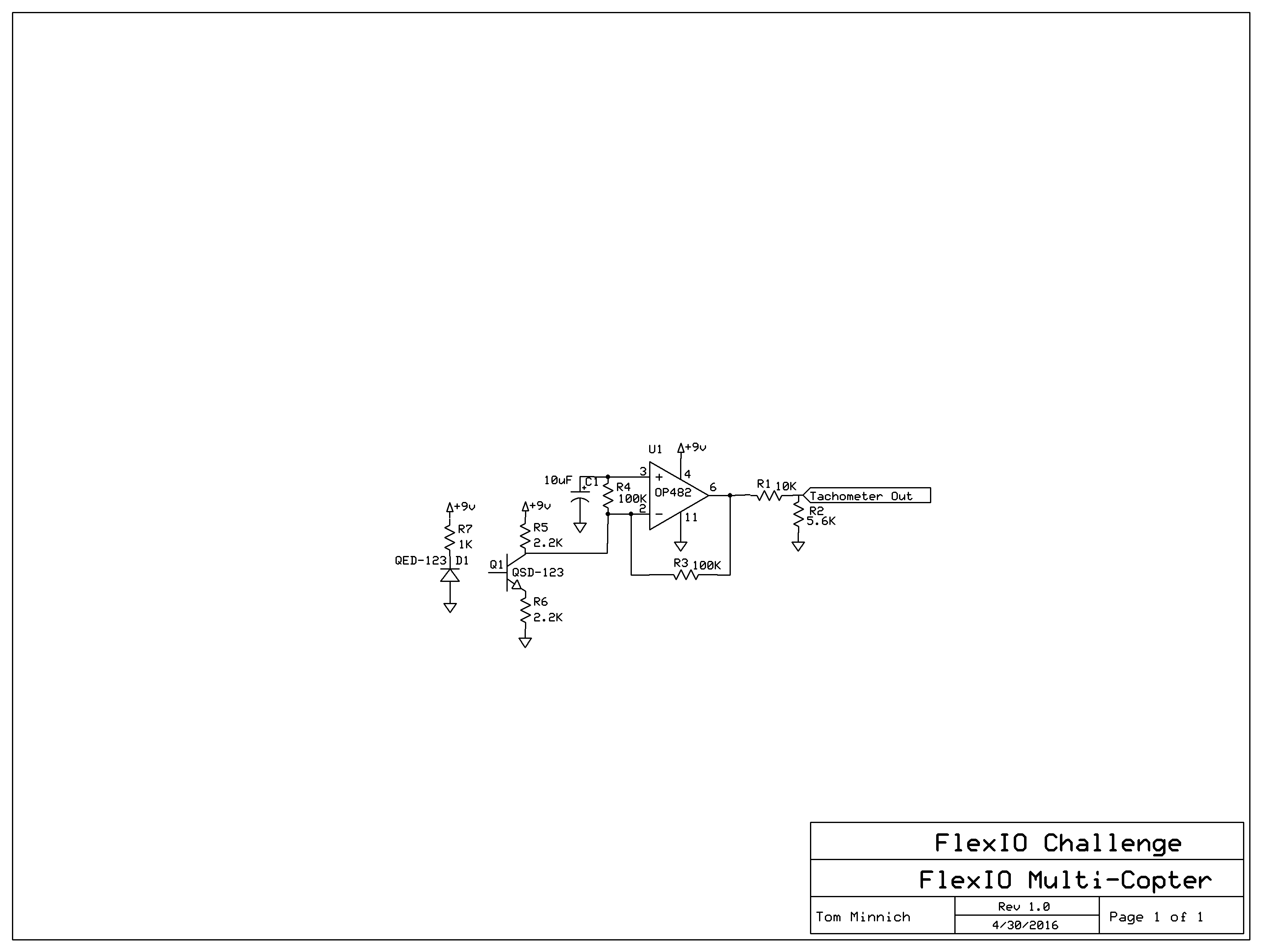
Very inexpensive infrared photodiode emitter and phototransistor pairs are used to detect the propeller rotations. A simple operational amplifier circuit is used to create logic level tachometer signals for the FRDM-K82F. The sample circuit is for a channel monitoring one propeller, and is duplicated for the 8 propellers. The capacitor C1 on the non-inverting terminal of the op amp is charged through a 100K Ohm resistor. The voltage on the capacitor is the average of the signal on the inverting terminal over the past second or so of time. The gain on the infrared sensor signal from the inverting terminal to the output of the amplifier is about 50. There is a resistor network on the output to insure the output remains 0 to 3.3 Volts for input to the FRDM-K82F, to avoid damaging the inputs with voltage outside of proper input limits.
The output of the circuit, the scaling is from a 10x oscilloscope probe.
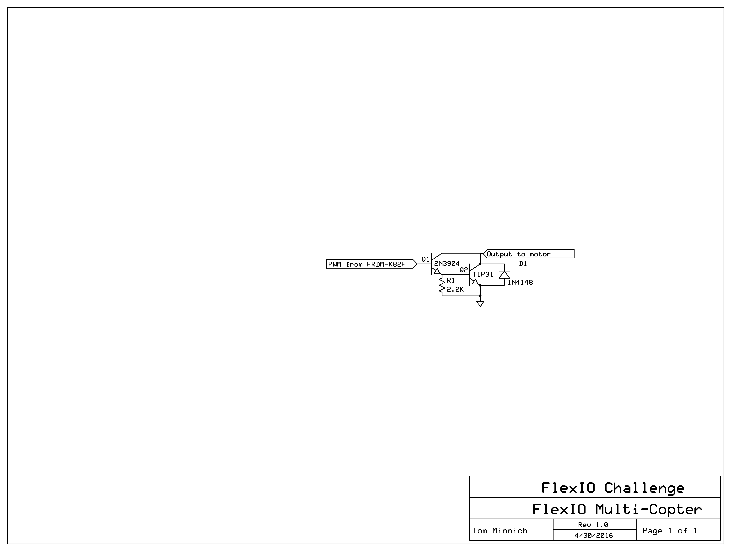
The Darlington Power Amplifier Stage
The following circuit, is an example of one channel of a PWM driver, and is used to drive the DC motor. The transistors were the types that I had at hand and may not be optimal, for instance, there is more drive capacity than is perhaps needed for the small DC motors being used. The circuit is duplicated to drive 8 DC motors.
What is PWM software trigger and why do we care?
It took a little searching to learn the need to call the software trigger function to cause the PWM duty cycle to update. Of course, without the call to the software trigger function the PWM duty cycle will not update, which is disappointing when you are trying to control propeller velocity.
//software trigger the PWM output changes
FTM_HAL_SetSoftwareTriggerCmd(g_ftmBase[flexTimer1_IDX], true);
FTM_HAL_SetChnCountVal(ftmBase, 0, pwm_duty_cycle[0]);
The need for a channel 6
The Flex timer module on the chip had no I/O pin available on channel 6. So a TPM channel is initialized to fill in for this gap. The PWM frequency is 25 kHz. I found it useful to use lower level HAL functions to access the full resolution available in the PWM duty cycle. So the Flex Timer module and the addition TPM channel provide the 8 PWM channels needed to control 8 DC motors.
Detecting Propeller hits!
This code snippet is from the velocity control loop and executes 20 times a second. It is a very simple technique to detect stopped or stalling propellers. A more sensitive scheme might be used at some future point, but this is sufficient for demonstration purposes. The commented out code is an option for cutting the power to a failed rotor, and is not used at this point.
if(inst_rpm[i]< (target_rpm[i]/2)){
	fail_count[i]++;
	if(fail_count[i]>10) rotor_fail[i] = true;
	// take needed action on rotor failure(s)
	//if(pwm_duty_cycle[i]>0)pwm_duty_cycle[i]--;
			}else{
	rotor_fail[i] = false;
	fail_count[i] = 0;
}
The debug print in a background processing loop, picks up on the rotor_fail error condition and prints a warning about the condition.
if(sec_tick_byte){
		 sec_tick_byte = false;
	     GPIO_DRV_TogglePinOutput(LEDRGB_GREEN);
	     for(dbg_loop=0;dbg_loop
	    	 debug_printf("Rotor #%d rpm =  %d   PWM CMD = %d \r\n",dbg_loop+1,inst_rpm[dbg_loop],pwm_duty_cycle[dbg_loop]);
	     }
	     if(rotor_fail[0]) debug_printf("Rotor #1 FAILURE!!!\r\n");
	 }
FRDM-K82F Wiring Designations
Channel Tachometer IN PWM Out
0 J4-2 J4-6
1 J4-4 J4-8
2 J4-12 J1-1
3 J4-10 J24-4
4 J12-16 J2-6
5 J12-15 J22-5
6 J12-14 J1-5
7 J12-13 J22-7
Experimentation
The original configuration which added 8 motors for a total of 12 motors including the Hubsan quadcopter, was just too heavy! The motors would need to spin faster than 25000 RPM to achieve flight. There were two options 1) lighten the original configuration in the total combined weight of the frame and electronics OR 2) Add more thrust by adding larger motors. Option 2) was chosen, because I liked the size and strength of the frame, I hated the idea of weakening the frame. and I had the motors already from another project.
Testing on June 4, 2016 showed a great increase in the available thrust. A 30 Amp. Turnigy electronic speed controller and a separate radio control is used for setting the speed of the two main rotors. The flight concept is the same in that the main rotors provide the neutral buoyancy, and the remaining motors are used to control the flight path.
Further Testing
Further tests showed the tendency for multi-copter to tip over when the speed of the rotors was slowly increased. The only alternative for flights free of constraints is to rapidly increase the speed of the rotors, to jump free of the ground. Rapidly speeding up the rotors was discarded as an idea because I wanted more than one test flight!
Constraining the Flight Path
Placing a plastic tube on the side of a vertical landing gear piece and using the tube to slide over stretched cord, provides the constrained flight path desired. Multi-copter is free to rotate around the stretched cord and the tube slides up and down. So hovering and other aspects of stabilizing the flight can be further studied, in a manner much more safe to the multi-copter and the test pilot. Bungee cords provide tension to the stretched cord.
A button provides a limit to the upward travel of multi-copter, to prevent ceiling crashes. A second elastic stretchy cord makes the limit to upward travel a soft limit and not a hard limit to travel that could damage multi-copter. Last of all, a foam cushion is added for the multi-copter to land upon.
Flight Test!
Future Experiments
More sophisticated control schemes will follow in later implementations. A scheme I will likely try will add electronics to measure the quadcopter’s rotor velocities and copy the propeller velocities of quad-copter rotors to the nearest pairs of propellers in the framework. In this way, a more maneuverable multi-rotor will result. Other possibilities include making larger prototypes using larger brushless motors.
Things in the Current Design that Need Work
If the small motors are run with much power this can interfere with the pairing of the Hubsan QuadCopter to its radio control transmitter. Improving the layout of the wiring and/or using brushless motors would help prevent the interference problem.
Advice for Those Replicating any of the Experiments
1) WORK SAFE!
View propellers as rotating saw blades!
Use eye protection of some sort while testing!
Fix any known problems before attempting any flight! Any problem will get worse in the air!
Do not work tired, or when you are distracted in any way!
Watch out for curious bystanders or pets when testing!
Never test alone! Always have an assistant standing nearby!
These ideas are drawn from experience flying radio control aircraft. The Academy of Model Aeronautics is a great resource for safety information and building techniques! Check out these resources at www.modelaircraft.org
2) Minor Details
Painting the propellers flat black helps to prevent false reflected infrared light signals from reaching the phototransistors. This causes noise in the measured speed of a propeller.
Project Conclusions
The project has been a rich set of opportunities to learn FlexIO module, processor Expert , the Kinetis SDK and also learn how to build and test a multi-copter.


Comments
Please log in or sign up to comment.