(This project is being managed here: Project Repository)
Programmable cards and badges are really good ice breakers at conferences as they're a great way to showcase your interests and skills. Packed with features and easter eggs, hackable PCB cards and badges have become customary to bring to the PCB Design conventions and hackathons now a days.
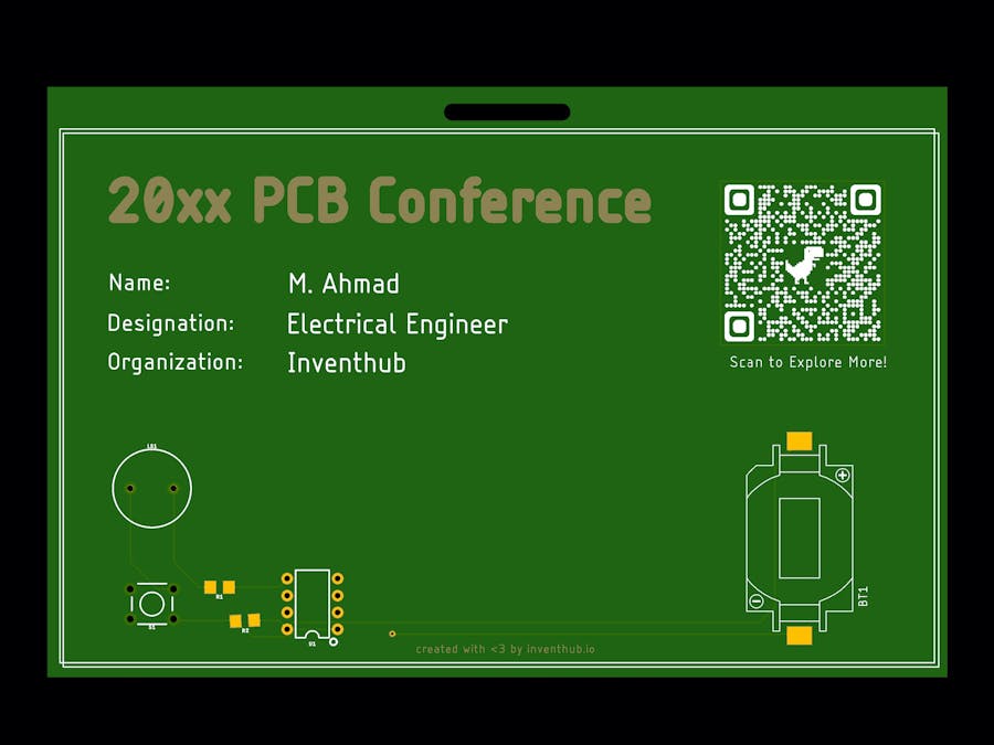
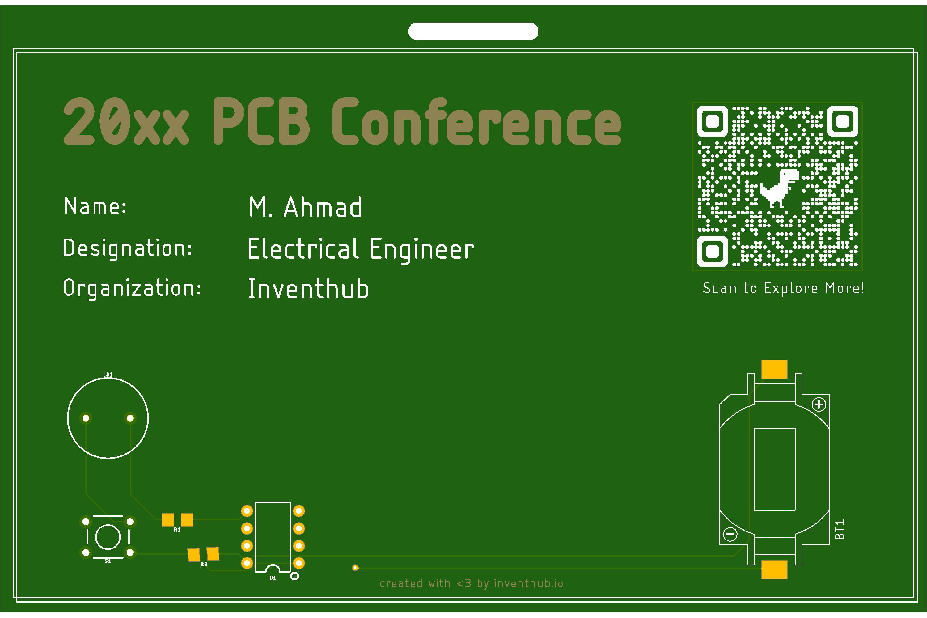
This project features a simple PCB Card just to give you an idea of what's possible and how easy it is to get started with your own PCB Card. I created this project using Inventhub, as it provides a git based version control, visual diffing of PCB and Schematic designs and a convenient library manager, all in one platform.
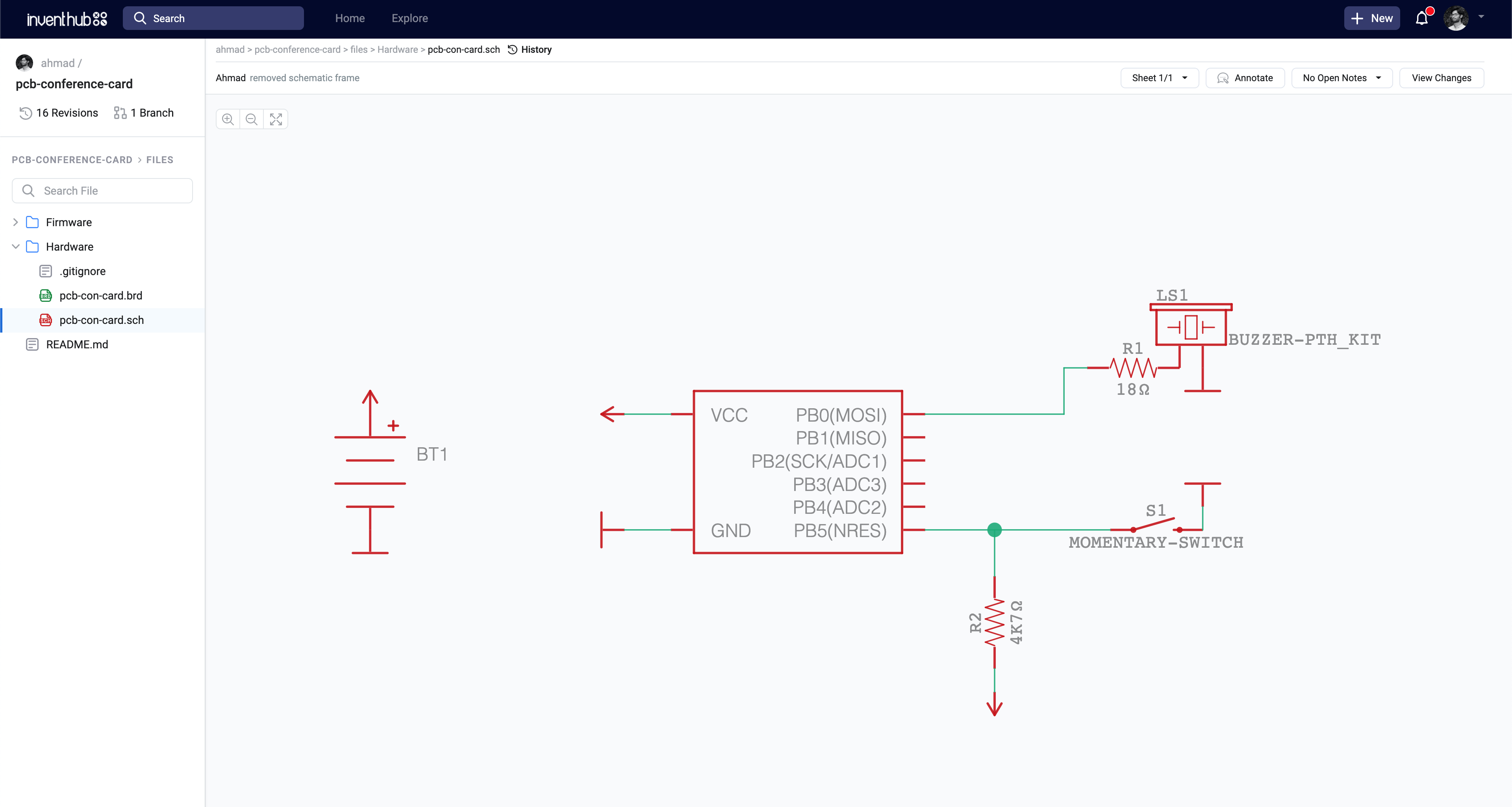
It has simple circuit based on an ATTiny85 microcontroller that can play the good old RTTTL tunes. The Ring Tone Text Transfer Language (RTTTL) was developed by NOKIA for making and customising ringtones in the cellphones like the 3310 and 1280.
Ring Tone Text Transfer Language (RTTTL)The RTTTL tone string has three parts i.e. name, value and data, each separated by the colon (:) and it looks like this:
"The Simpsons:d=4,o=5,b=160:c.6,e6,f#6,8a6,g.6,e6,c6,8a,8f#,8f#,8f#,2g,8p,8p,8f#,8f#,8f#,8g,a#.,8c6,8c6,8c6,c6"- Name: The name of the tone - limited to 1 - 10 characters.
- Value: It's a set of comma separated values that set some default parameters for the execution of the tone.
- Data: All the notes and keys to be played in the tone arranged as a set of comma separated values.
[Checkout the schematics HERE]
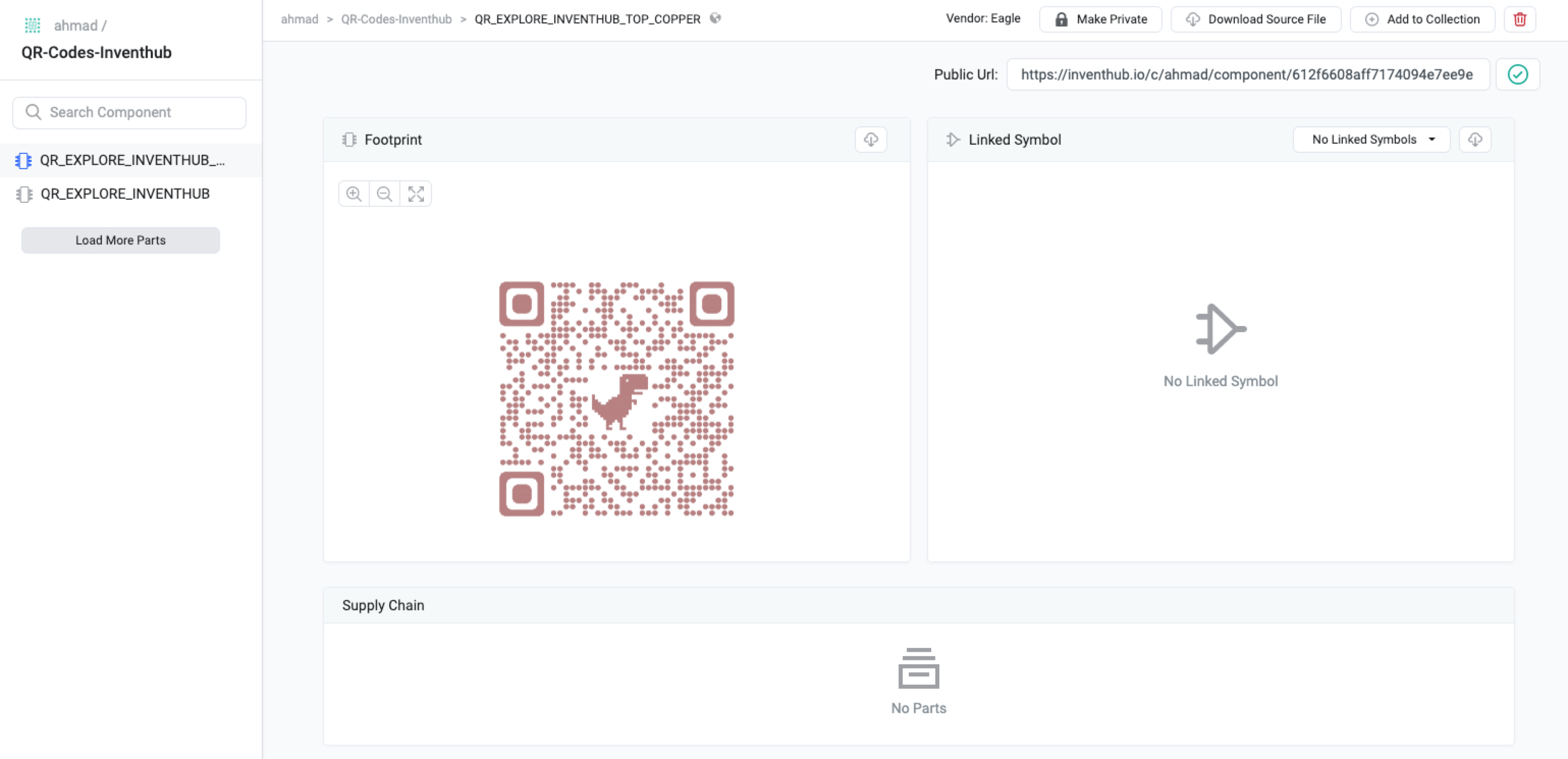
While designing PCB badges, business and conference cards, graphics are very important. You can get creative or just add images, icons, QR codes and logos. But adding Graphics using Eagle CAD is a bit tricky. Our PCB features a QR Code that redirects you to the InventHub Community where you can explore many amazing open source projects. That QR footprint is being managed via InventHub's library Manager. You check that here:
QR-Code Library Footprint: https://inventhub.io/c/ahmad/component/612f6608aff7174094e7ee9e
- Convert your graphics (png, svg, jpeg etc) to a monochrome BMP formate.
- Create a new library in eagle CAD and create a new footprint.
- In the footprint editor, run the following command:
run import-ulp.bmp - The above command opens up a menu to load the BMP file, set the colour options and the PCB layer for the graphics.
- Once you're done, click
run-scriptand this will add the graphics to the footprint which you can use in the design.
The standard dimensions of a conference card are generally 5.3 x 3.5 inches. So, the first step is to resize the PCB board. Once the board size is according to your requirements start adding components and making holes in the board. These kind of projects challenge your creativity as there's a bit more emphasis on the aesthetics along with the functionality so you'll find yourself making a lot more changes in the design than you think.
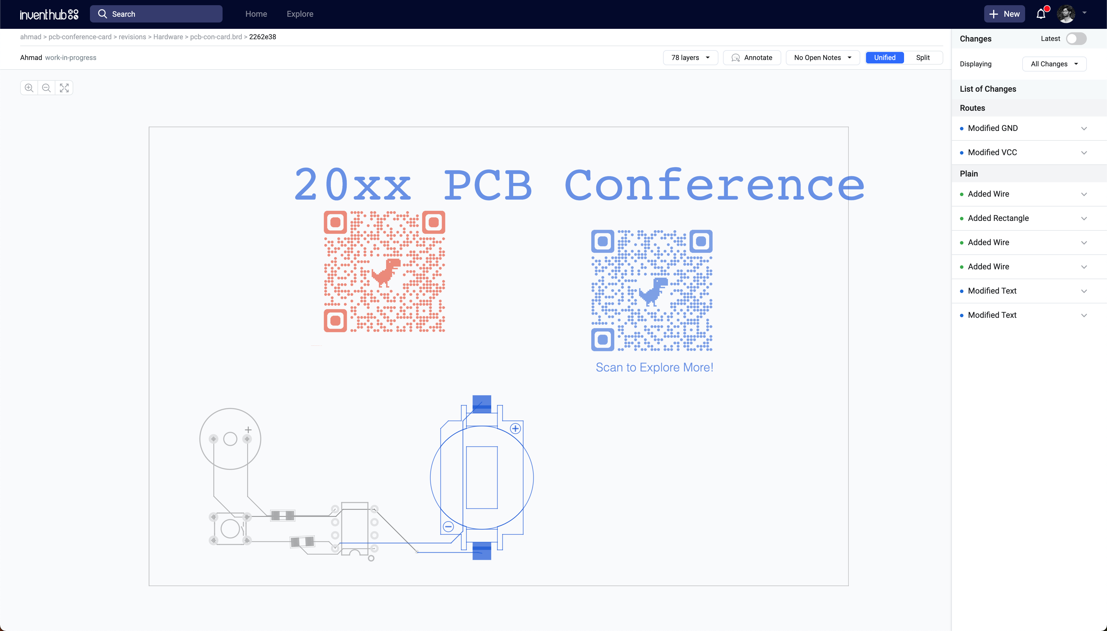
Fortunately, you can visually compare any two variations or layouts of the design using Inventhub. The visual diffing of the PCB design highlights all the changes between any two commits and colour codes every change to represent the new, modified and deleted elements from the design. This is specially useful while rearranging the designs as you go through all the iterations.
You can also mark issues, communicate with your collaborators, or just take notes right on top of the PCB or Schematic design using the annotations. It's very helpful while working with your teammates or collaborators as you can easily collaborate on the same files in the same project without having conflicts.
After finalising the PCB design, I created the release of the project with Inventhub's release management tool. Here you can manage, review and approve/reject releases for your projects. It also creates a zip file containing a snapshot of all the project files at the time of release creation so that any further changes in the project itself don't affect the release product without any review or approval.
Finally, to get the PCBs manufactured, you can export the release zip containing the project files and send it to your preferred PCB fabrication service.
While the PCBs are being manufactured, you need to order all the components required for the project. So, when the manufactured PCBs arrive, you better be ready to solder everything on the board and get it up and running ASAP.
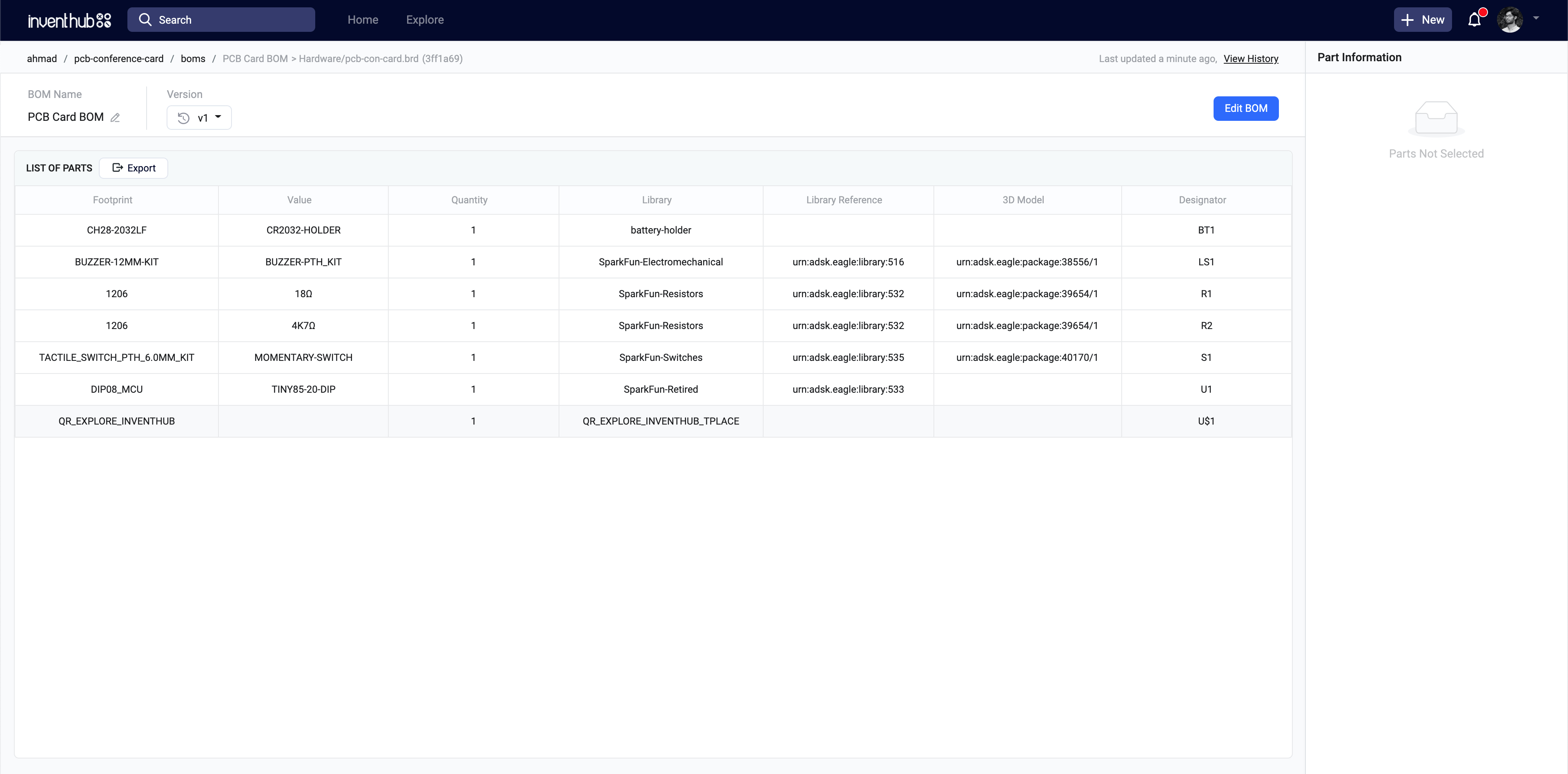
This is where the BOM or Bill of Materials comes into play. It's a list of all the components used in your project along with all the relevant details like the standard manufacturer's part numbers (MPNs) and required quantities for each component. Instead of manually arranging all this data into excel, you can just go to BOM tab on the project on Inventhub and generate a standard BOM for your PCB design automagically. You can just export the BOM as a standard CSV file and send it to your components provider.
As we're using the barebones microcontroller and not a development board, you would need an AVR programmer to flash the firmware on your ATTiny85 chip. You can also create your own AVR programmer. To do that, checkout this awesome project by Arnov Sharma:
or you can also turn an Arduino UNO to an ISP to program the ATTiny. Checkout this instructable on how to do this.
The project was originally inspired by Dimitris Platis's project on Hackster.io where he created a hackable trophy for a hackathon competition.






Comments
Please log in or sign up to comment.