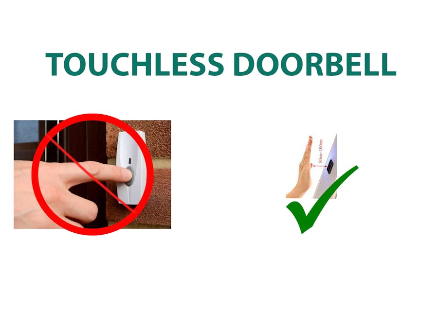
Social distancing is the one of the best method to escape from COVID-19. I strongly recommend to stay at home. But we can't avoid some emergency visits to some homes. When we arrived at infront of a house, first we search the doorbell button/ calling bell button. And press the button. But in this special situation this doorbell button can cause the virus to spread. When some infected person press the button the virus hold on that button and when a non infected person touch this button the virus spread to that person. We can avoid this danger by using the touchless doorbell. The existing doorbell can convert to a touchless doorbell.
The updated version is published on Instructables. Click here to read
How it works?When show our hand infront of IR Sensor, The sensor will send signal to Arduino board. And Arduino drive the relay. Relay is connected with doorbell. And finally the bell will ring.
In this article,
- Explain the working of IR Sensor Module.
- Interface the IR Sensor Module
- Control the relay module with Arduino Uno
- Explained each line of code.
Before starting we need to know about the IR Sensor module.
IR Sensor ModuleIR Sensor Module is a IR based proximity sensor. Mainly it consist of an IR LED, Photo diode, LM358 operational amplifier IC, Variable resistor.
Pinout
There are three pins in this sensor module.
Vcc - Power supply input (5V)
GND - Power supply ground
OUT - Output pin (Active HIGH)
WorkingThe IR LED transmitter transmit the light in the range of Infrared frequency. The wave length of IR wave is greater than the wave length of visible length. The photodiode receiver will receive this transmitted IR light. It only conduct when a light fall on it. And it's reverse biased. And the current flow is directly proportional to the amount of light falling on it. Here the LM358 Operational amplifier (Op-amp) in voltage comparator mode. The comparator will compare the threshold voltage set using the variable resistor and the photodiode's series resistor voltage (PSR Voltage). Op-amp out put is connected to the "OUTPUT" pin.
PSR Voltage drop > Threshold Voltage - Output is HIGH
PSR Voltage drop < Threshold Voltage - Output is LOW
The variable resistor is used to calibrate the distance at which object should be detected.
Keypoint
When the object present infront of the sensor, the sensor output is HIGH, Otherwise it is LOW
This key point will help to us in programming part.
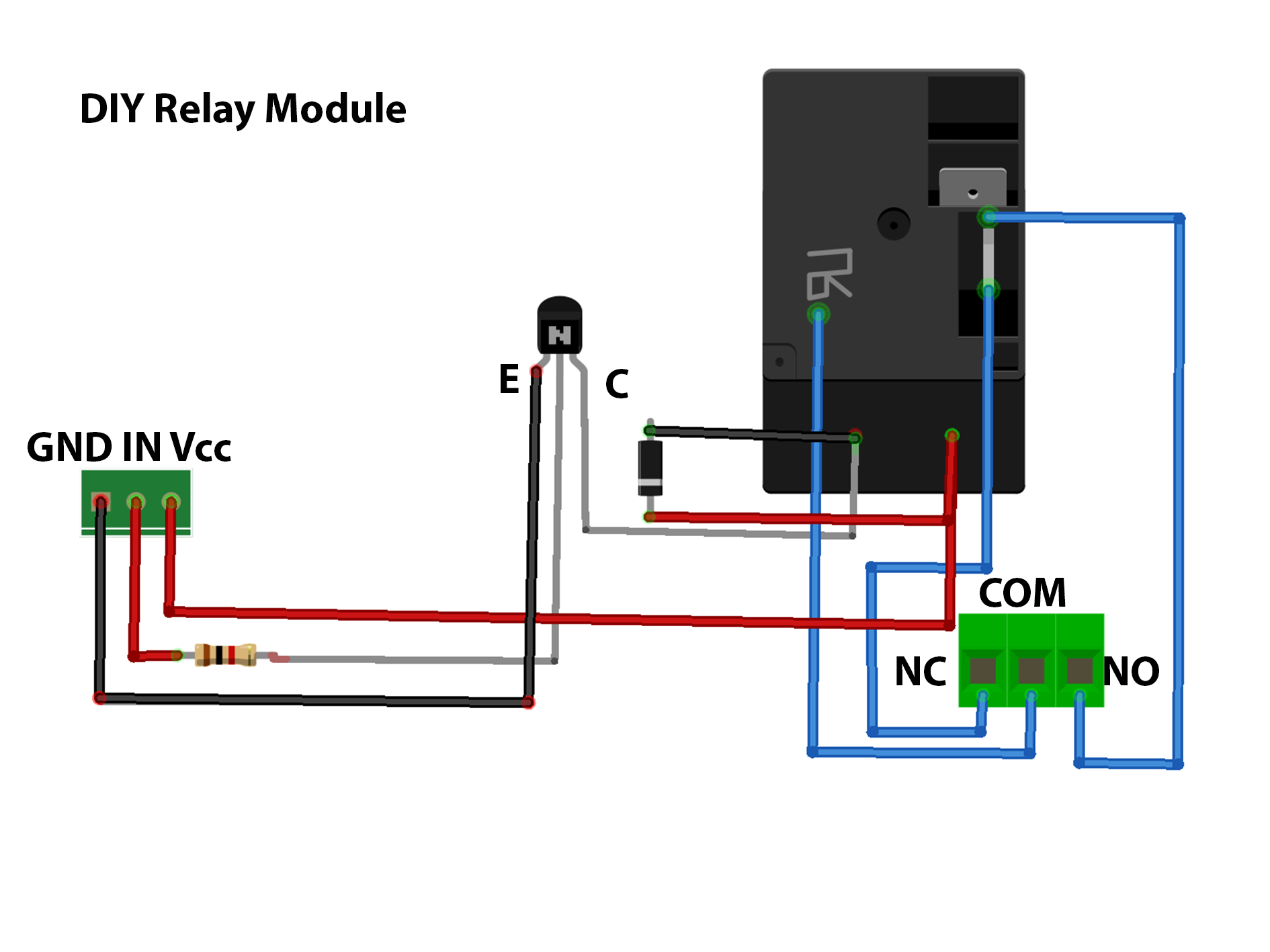
Relay ModuleThe main part of the relay module is relay. The microcontroller cant directly deal with high voltage. So relay is act as an inter mediator to microcontroller and other high voltage devices. Relay are switches that open or close circuit electronically. You can buy a relay module from the link given in the components part. Alternatively you can make your own. The circuit diagram is given in the endof this article
Relay module have three pins and three screw terminal.
Pins
Vcc - Power supply input (5V
GND - Power supply ground
IN - Signal from microcontroller (here Arduino)
Screw Terminals
NO - Normally Open
COM - Common
NC - Normally Closed
Let's start the programming part.
Step - 1
Open Arduino IDE
Here I am not using any library. First we need to program the setup part. Here I am going to use digital pin 2 to read the IR sensor module. So we need to set it as "INPUT". And digital pin 13 to control the doorbell via relay. So set it as "OUTPUT". The two job is done with "pinMode()" function.
void setup(){
pinMode(2,INPUT);
pinMode(13,OUTPUT);
}
Step - 2
Now I am going to code the loop part. Here we want to write the pin 13 (relay pin) only the pin 2 (IR Sensor pin) is "HIGH". Otherwise the pin 13 set as "LOW". For that we use an "if" and "else". Here we use the function "digitalRead()" to read the IR Sensor.
void loop(){
if(digitalRead(2)==HIGH){
digitalWrite(13,HIGH);
}
else{
digitalWrite(13,LOW);
}
}
The coding part is completed. The complete code is given in the end of this article. Upload the code to Arduino board
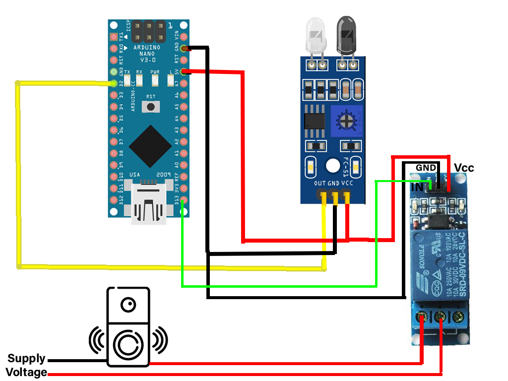
Next we need to wire the circuit.
Arduino Nano digital pin 2 - OUT pin of IR Sensor
Arduino Nano digital pin 13 - IN pin of Relay Module
Arduino Nano digital pin 5v - Vcc of Relay Module
Arduino Nano digital pin 5v - Vcc pin of IR Sensor
Arduino Nano digital pin GND - GND of Relay Module
Arduino Nano digital pin GND - GND pin of IR Sensor
NC of Relay Module - One terminal of Doorbell
COM of Relay Module - To supply voltage of Doorbell.
You can see the circuit diagram at the end of this article. Here I connect more than one connection from one header pin of Arduino. For that make a "T" connection with jumber wire and connect it to Arduino and Other devices.
Please don't copy-paste my code. Understand the code and make your own
You can join our telegram group here or search INNOVATION.
STAY HOME, STAY SAFE, STAY CREATIVE. Let break the chain.
You can also do this project without Arduino or any microcontroller. Connect the "OUT" pin of IR Sensor module to the "IN" pin of Relay Module. In this article I use the Arduino. Because this article also discuss about the "Interfacing of IR Sensor Module with Arduino". This is also the part of my series of project for beginers.
Follow me on,
Instagram : five_volt_player
Facebook : Akshay Joseph
Github : akshayjoseph666
Contact : akshayjoseph666@gmail.com
Share your experience and suggestions on the comment box.
Previous articles :
Interfacing Bluetooth Module (HC-05) with Arduino Uno , Automatic Water Tap , Automatic Hand Sanitizer , Interface Ultrasonic sensor with Arduino Uno , Control Servo motor with Arduino Uno and Pushbutton , Control Servo motor with Arduino Uno and POT , Servo Motor Interface with Arduino Uno , IR Controlled Home Appliances With Saving Previous State , Touchless Hand Wash Timer


Comments