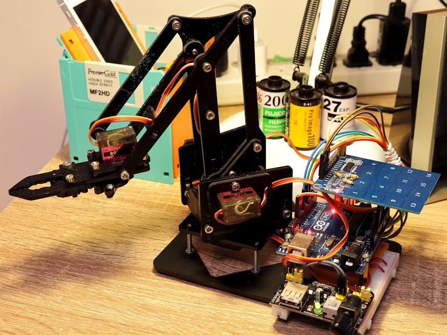
After returning the MeArm I borrowed from my former company, I wanted to build one for my own and make use of the spare touchpad. This project uses a dusty Arduino Uno Rev3, an old MB102 power supply module and the TTP229-BSF.
There are already many MeArm wiring tutorials and assembling guides exist, so I won't go for these details. Just remember to calibrate your MeArm properly.
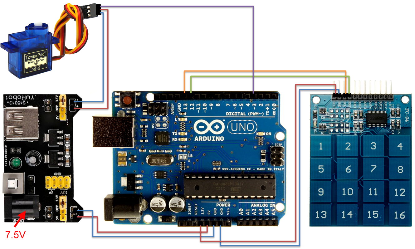
Servo signal cable:
- Servo 1 (base servo) -> Pin 3
- Servo 2 (right servo) -> Pin5
- Servo 3 (left servo) -> Pin 6
- Servo 4 (claw servo) -> Pin 9
TTP229-BSF:
- VCC -> 3.3V
- GND -> GND
- SCL -> Pin 13
- SDO -> Pin 12
The MB102 output 5V (750mA) for Arduino Uno (powered via its 5V pin and another GND) as well as all servos.
Since the whole system is connected together, connecting Arduino and PC with a USB type-B cable also works (the 5V pin is said to be able to output 500mA). However, since mini servos may draw 100-200mA, using MB102 is probably still a better idea.
The MB102 is powered via a 7.5V 1A charger. The MB102 needs at least 6.5V to be able to provide steady 5V output.
In order to minimize the chance of accidentally touching nearby keys, I selected keys in separate places. However it is possible to assign any keys you want in the code. Servo pins and turning speed is also adjustable.
The touchpad should avoid other things too, for it's also sensitive for touches from sides or under.
How to read TTP229-BSF
Unlike its I2C-version brother TTP229-LSF, the BSF version uses a rather simple 2-wire serial protocol.
First you need to set the hardware to enable 16-key / multiple key mode:
Connect P1-3 (TP2), P1-4 (TP3) and P2-5 (TP4) with resistors. Here I used 10KΩ ones.
(Originally I used simple wires, but the keypad didn't work well in that case. And the datasheet actually said the modes are "selected via high-value resistor(s)".)
TP2 set it to 16-key mode and TP3/TP4 set it to multiple key mode (that you can press more than one keys at the same time).
The protocol is as below:
So: you pull the SCL pin low than high 16 times, and the SDO pin would respond as pulling low (key i+1 pressed) or high (key i+1 not pressed).
#define SCL_PIN 13
#define SDO_PIN 12

int keypad[16];

void readKeypad() {
 for (int i = 0; i < 16; i++) {
   digitalWrite(SCL_PIN, LOW);
   keypad[i] = digitalRead(SDO_PIN);
   Serial.print(keypad[i]);
   digitalWrite(SCL_PIN, HIGH);
 }
 Serial.println("");
}

void setup() {
 Serial.begin(9600);
 pinMode(SCL_PIN, OUTPUT);
 pinMode(SDO_PIN, INPUT);
}

void loop() {
 readKeypad();
 delay(100);
}
The code is based on this sketch (hooray for this nameless hero! There are simply too many over-complicated code online), however it can get only one key as result. I simply read all 16 responses of the SDO pin together and put them into an array.
If you open the serial monitor window you can see live status of all keys:


_ztBMuBhMHo.jpg?auto=compress%2Cformat&w=48&h=48&fit=fill&bg=ffffff)


Comments
Please log in or sign up to comment.