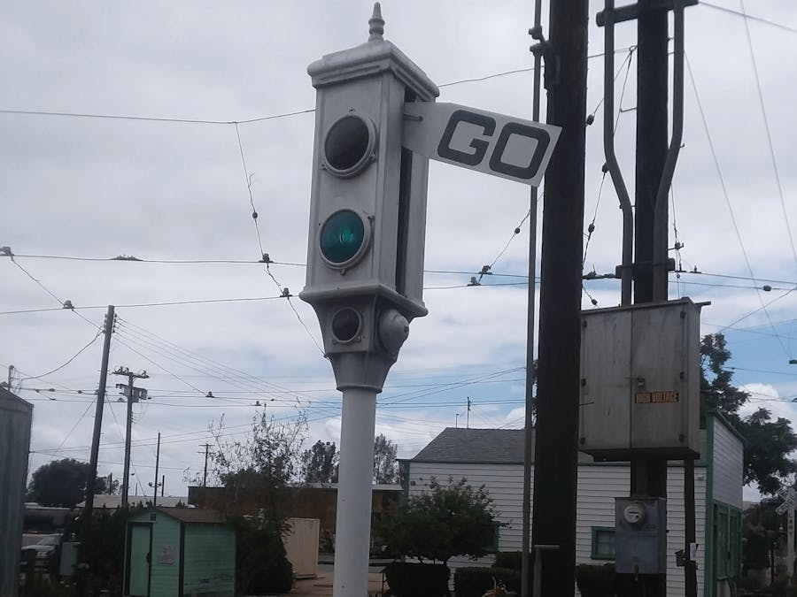
The Southern California Transportation Museum is one of the largest private transportation museums in the United States. We are privileged to have among our artifacts a set of Acme traffic lights. This type of traffic signal was deployed in the Los Angeles area in the 1920s and 1930s. This was the time when every city was experimenting with different types of traffic signals. Later the Automobile Club convinced everyone to adopt the three-light signal they use today.
During the brief time they were in use, the Acme traffic light became the favorite of the Hollywood cartoonist so, that's why you see them all over the movies. It’s the one with the arm and lights. The arms were used during the day since lights used electricity and electricity costs money. Then, at night the lights were used because, logically, you couldn’t see the arm.
The museum has one of the original Acme signal controllers – but it has a fatal design flaw, it thinks that it’s running a traffic signal. That means it will run it all day and night, wearing out the motors. So, the museum decided to replace the old controller with a new one consisting of a Raspberry Pi and a 16-channel relay module. The relay module was chosen because in the past it had provided reliable service in the museum’s signal garden. Also, because it is incredibly easy to program
The Raspberry Pi and the relay board must work in a somewhat harsh environment. The museum moved to Perris, CA because the hot dry climate is good for the artifacts. However, the climate is not good for the electronic parts. Most of the components sit in a cast iron box, painted black, with no ventilation, in a semi-desert. We are not certain of how hot it gets inside, but the 3d printed hinges we implemented in the box melted. Fortunately, all of the other parts are still working properly.
Now, you might be wondering why it takes so many relays to control one signal. The Acme traffic light is not a simple signal. There are arms, lights, and a bell. So, the relays are for:
- Red Light
- Green Light
- Yellow Light
- Motor power
- Motor direction
- Bell
- Fold (Keeps the arms from extending when returning them to the housing.)
And everything must be doubled because we have two signal heads.
Some additional relays were needed since the arm motor works by shorting two wires and applying power to a third. To change direction, you change which wires are shorted and which gets power. This would have been possible with two relays on the 16-channel board, but in this configuration, it would be possible for a software glitch to damage the motor. To ensure that would not happen we used a DPDT relay which provided a hardware interlock. Also, the motor, fold magnet, and bell all use big A/C coils. When these are turned off they generate a huge electric pulse. This does nasty things to the Raspberry Pi. (Funny enough the board has no problem.) To get around this problem three zero crossing solid state relays were added. By turning off the coils when no voltage is present you avoid the pulse problem.
Railroad equipment is designed to last a long time. The last railroad relay I used had an inspection sticker on it of 1910 (that’s when it was taken out of service, not when it was made). I don’t know if the new parts will last as long, but so far, the new parts have been very reliable in a challenging environment.


Comments
Please log in or sign up to comment.