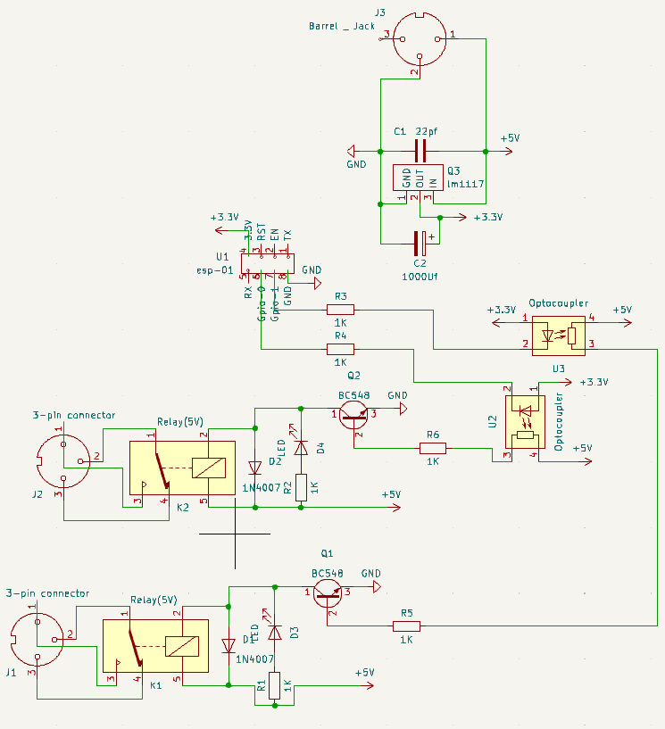
Module Overview:The ESP-01 S is a compact relay module equipped with a built-in power supply, designed for various automation and control applications. This guide will walk you through its features, programming steps, firmware options, ordering instructions, and common use cases.
- On-Board Power Supply: Supports power input from 220V to 12V or 5V, depending on your requirements.
- Dual Relay Control: Can control two separate relay modules simultaneously.
- 12V to 5V Relay Support: You can use 12V to 5V relays with an appropriate power supply.
- On-Board Programming: Allows programming via RX and TX communication, requiring a USB to TTL converter.
- Versatile Power Options: Can be powered by both DC and 220V sources.
- Compact Form Factor: Small size measuring 4.8cm x 4.2 cm (48.28 x 42.54 mm).
- Mounting Holes: Four mounting holes are provided for easy installation.
- Disconnect any load connected to the relay module.
- Power the board via AC or DC supply (DC is recommended).
Connect the following between the USB to TTL converter and the module:
- Connect the following between the USB to TTL converter and the module:Connect RX of the converter to TX on the module.Connect TX of the converter to RX on the module.Connect GND of the converter to the GND on the module.
- Press the Push Switch once to enter programming mode (a relay will click).
- Then press the reset switch once.
- You should now be able to program the ESP-01 S using the module.
- After programming, press the push button and reset switch to run the programmed code.
Ready to Load Firmware:Two firmware options are available for the ESP-01 S:
- Async Webserver for ESP-01 S: This firmware enables control of the board via WiFi using a web interface.
- ESP-01 S Automation using MQTT: This firmware connects the board to an MQTT broker, allowing remote control from anywhere.
- Download and extract the GitHub files related to the ESP-01 S module.
- Locate the Board Gerbers in the Gerber folder.
- Upload the Gerber zip file to your chosen PCB manufacturer (JLCPCB is recommended).
- Proceed to place your order.
- Upon receiving the PCB, you will need to cut it along the provided guide lines on the board to obtain two separate copies.
- If you plan to power the board only with a DC power supply, you can skip mounting the SMPS (Switched Mode Power Supply) and directly power it through the DC jack. Alternatively, you can cut the Hilink SMPS section of the board (this step is optional).
Use Cases:The ESP-01 S relay module is well-suited for various applications:
- Automation systems where remote control is required.
- Space-constrained areas due to its compact size.
- Projects that demand easy programming and automation solutions.
- Provides a cost-effective solution for control and automation needs.
By following these instructions and guidelines, you can effectively utilize the ESP-01 S relay module for your specific automation and control requirements


_4YUDWziWQ8.png?auto=compress%2Cformat&w=48&h=48&fit=fill&bg=ffffff)


_Ujn5WoVOOu.png?auto=compress%2Cformat&w=40&h=40&fit=fillmax&bg=fff&dpr=2)


Comments