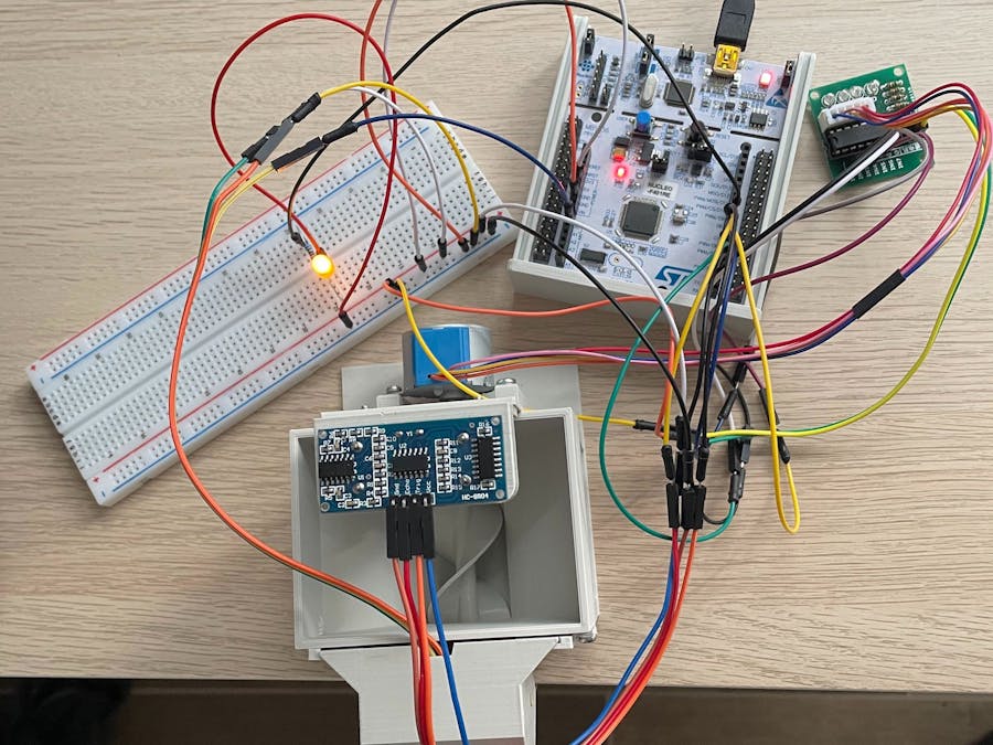
The idea was born from the need to feed my dog automatically or manually from remote places. Being the one who takes care of him, I wanted a way to make him happier even when I am studying at university. So I built an IoT system in order to let him have his treats all day long.
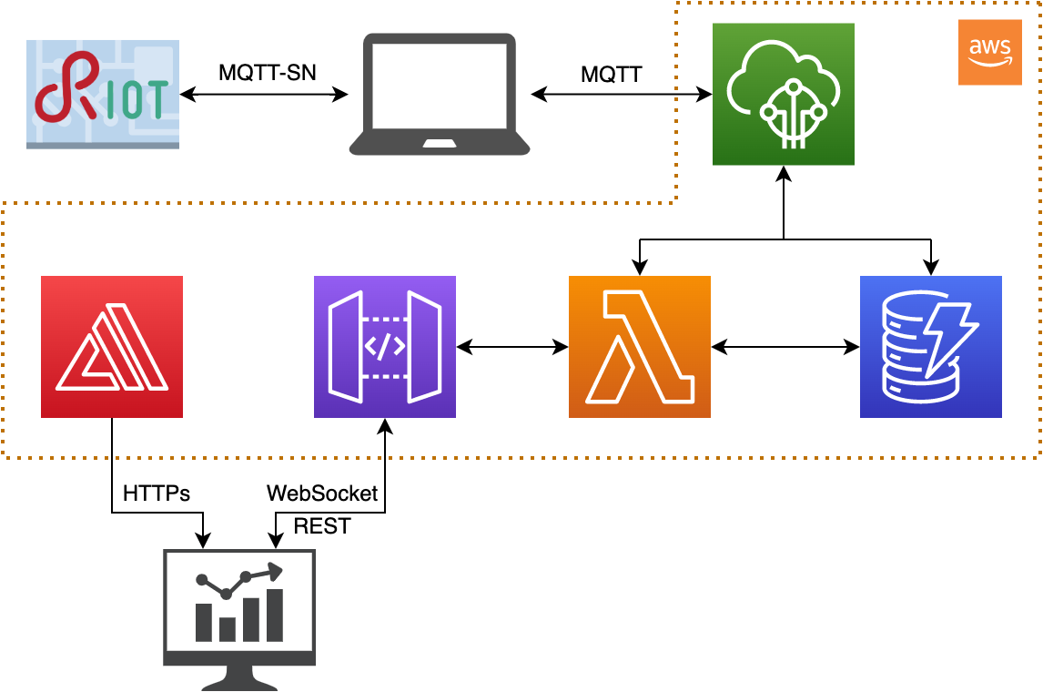
The IoT system I built is composed of a device and a cloud computation part. The device collects information from a set of environmental sensors and interacts with the environment using actuators following the 'Sense-Think-Act' paradigm.
I used a STM NUCLEO-f401re board with an ARM cortex M4 core running RIOT-OS. RIOT is a free and open source operating system with real-time and multi-threading capabilities. It supports a range of devices that are typically found in the Internet of Things (IoT): 8-bit, 16 bit and 32-bit microcontrollers.
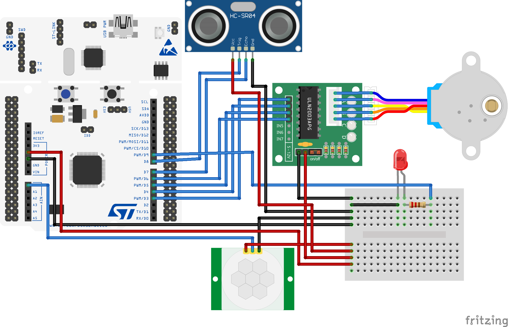
The board is connected to the following sensors and actuators:
Ultrasonic sensor
HC SR04 - datasheet
It measures the fill level of the dispenser. It is put on top of the food container and measures the distance from the food. While it is dispensed, the level goes down and the ultrasonic measures bigger distances.
After it has been activated, this sensor returns an echo back whose pulse width (uS) is proportional to the distance measured. This value can be divided by 58 to obtain the distance in cm. The resolution is 0.3cm and the minimum distance that can be measured is 2cm. For that reason, the sensor was placed 2cm above the maximum fill level of the food container.
When the container is empty the sensor is going to measure the distance from the screw. This distance will depend on the current rotation position of the screw, so values bigger than the threshold (5.69cm - 330uS) will be considered as empty level. The container will be considered filled when the sensor measures a distance equal to 2.59cm (150uS).
Code
First I initialized the GPIO pins needed by the sensor. The trigger pin is initialized as a simple output pin. The echo pin is initialized in order to call a callback function whenever the input value of the pin changes:
gpio_init(trigger_pin, GPIO_OUT);
gpio_init_int(echo_pin, GPIO_IN, GPIO_BOTH, &echo_cb, NULL);
We also need two global variables to store times:
uint32_t echo_time;
uint32_t echo_time_start;
The read function sends an impulse to the sensor to activate it. Then it waits 100 milliseconds before reading the values written by the callback function:
int read_distance(void){
    echo_time = 0;
    gpio_clear(trigger_pin);
    xtimer_usleep(20);
    gpio_set(trigger_pin);
    xtimer_msleep(100);
    return echo_time;
}
The following function is activated when it detects a change on the echo pin. It measures the difference between the starting time (when the ultrasonic pulse is transmitted) and the stop time (when the ultrasonic pulse is received back):
void echo_cb(void* arg){
    int val = gpio_read(echo_pin);
    uint32_t echo_time_stop;

    (void) arg;

    if(val){
        echo_time_start = xtimer_now_usec();
    }
    else{
	echo_time_stop = xtimer_now_usec();
	echo_time = echo_time_stop - echo_time_start;
    }
}
PIR motion sensor
HC SR501 - datasheet
It checks if the dog is walking past the food dispenser. This sensor is always on. When it detects movements inside the range of a 110° angle and 5m distance, a 3.3V impulse of 3 seconds is sent to the analog pin. Every second the value emitted by the sensor is read from the board and if it is high (it has detected movements) it triggers the stepper motor.
Code
I initialized the analog line from which the board receives the value:
adc_init(ADC_LINE(0));Then I used the following simple function to read the value:
int read_pir(void){
    int sample = 0;
    sample = adc_sample(ADC_LINE(0), ADC_RES_8BIT);
    return sample;
}
Stepper motor
28BYJ 48 - datasheet
ULN 2003 driver - datasheet
It rotates a screw which dispenses the food.
Code
I inizialized the pin needed by the actuator:
gpio_init(pin_step_1, GPIO_OUT);
gpio_init(pin_step_2, GPIO_OUT);
gpio_init(pin_step_3, GPIO_OUT);
gpio_init(pin_step_4, GPIO_OUT);
Then I wrote this function following the specification of the stepper motor and the driver. It checks if it is already dispensing, then it makes the motor rotate and make 2000 steps. At the end it sets the variable need_check which means the ultrasonic sensor will be activated to measure the fill level:
void dispense(void){
    if (can_dispense) {
        can_dispense = 0;
        int steps = 0;
        int count = 2000;
        while (count) {
            switch(steps) {
                case 0:
                gpio_clear(pin_step_1);
                gpio_clear(pin_step_2);
                gpio_clear(pin_step_3);
                gpio_set(pin_step_4);
                break;
                case 1:
                gpio_clear(pin_step_1);
                gpio_clear(pin_step_2);
                gpio_set(pin_step_3);
                gpio_clear(pin_step_4);
                break;
                case 2:
                gpio_clear(pin_step_1);
                gpio_set(pin_step_2);
                gpio_clear(pin_step_3);
                gpio_clear(pin_step_4);
                break;
                case 3:
                gpio_set(pin_step_1);
                gpio_clear(pin_step_2);
                gpio_clear(pin_step_3);
                gpio_clear(pin_step_4);
                break;
            }
            steps++;
            xtimer_msleep(2);
            if (steps>3){
                steps=0;
            }
            count--;
        }
        gpio_clear(pin_step_1);
        can_dispense = 1;
        need_check = 1;
    }
}
Led
It lights on when the food container is empty.
I initialized the pin needed by the led:
gpio_init(led_pin, GPIO_OUT);Then I controlled it using the following GPIO functions:
gpio_set(led_pin);
gpio_clear(led_pin);When the PIR motion sensor detects a pet walking past the dispenser it sends an impulse to an analog pin which is read every second. When the impulse is detected a callback function is called and the stepper motor is activated to do 2000 steps and dispense food. A timer is set to disable the stepper for a certain amount of time and avoid it dispensing food every time the pet walks past. The user can also dispense food from remotely using a web dashboard.
After having dispensed food, the ultrasonic sensor is activated to measure the fill level of the food container. If the value is over a threshold the led is switched on to report that it needs to be filled. If the led is on but the container has been filled, it is switched off.
The full code can be found in the GitHub repository linked at the end of this post.
Network- From the board to the local broker
The board is connected to the laptop using RIOT ethos tool (Ethernet-over-serial). They communicate over this interface exchanging messages through MQTT-SN. I chose mosquitto.rsmb as broker because it implements both mqtt and mqtt-sn protocols. It has a bug reported by RIOT with link-local IPv6 addresses, so I assigned both the board and the broker a global IPv6 address. The board publishes on “topic_out” and subscribes to “topic_in” to receive messages from outside.
The following code is used on the board to initialize the connection with the broker:
static char stack[THREAD_STACKSIZE_DEFAULT];
static msg_t queue[8];
static emcute_sub_t subscriptions[1];
static char topics[1][64U];

void mqtts_init(void){
    msg_init_queue(queue, ARRAY_SIZE(queue));
    memset(subscriptions, 0, (1 * sizeof(emcute_sub_t)));
    thread_create(stack, sizeof(stack), EMCUTE_PRIO, 0, emcute_thread, NULL, "emcute");

    char * addr1 = "2000:2::2";
    add_address(addr1);
    char * addr2 = "ff02::1:ff1c:3fba";
    add_address(addr2);
    char * addr3 = "ff02::1:ff00:2";
    add_address(addr3);

    con();
}

static void *emcute_thread(void *arg){
    (void)arg;
    emcute_run(BROKER_PORT, "board");
    return NULL;
}

static int con(void){
    sock_udp_ep_t gw = { .family = AF_INET6, .port = BROKER_PORT };
    char *topic = NULL;
    char *message = NULL;
    size_t len = 0;

    ipv6_addr_from_str((ipv6_addr_t *)&gw.addr.ipv6, BROKER_ADDRESS);
    emcute_con(&gw, true, topic, message, len, 0);

    return 0;
}

static int add_address(char* addr){
    char * arg[] = {"ifconfig", "4", "add", addr};
    return _gnrc_netif_config(4, arg);
}
The following function subscribes to the topic used by the board to receive messages from outside. When it receives a message it is passed as parameter to the callback function on_pub which processes it:
static int sub(void){
    unsigned flags = EMCUTE_QOS_0;
    subscriptions[0].cb = on_pub;
    strcpy(topics[0], TOPIC_RECEIVE);
    subscriptions[0].topic.name = topics[0];

    emcute_sub(&subscriptions[0], flags);

    return 0;
}

static void on_pub(const emcute_topic_t *topic, void *data, size_t len){
    (void)topic;

    char *in = (char *)data;
    char msg[len+1];
    strncpy(msg, in, len);
    msg[len] = '\0';
    if (strcmp(msg, "dispense") == 0){
        dispense();
    }
}
The following function is used to publish messages.
static int pub(char* msg){
    emcute_topic_t t;
    unsigned flags = EMCUTE_QOS_0;
    t.name = TOPIC_SEND;

    emcute_reg(&t);
    emcute_pub(&t, msg, strlen(msg), flags);

    return 0;
}- From the local broker to Amazon Web Services
On the laptop connected to the board must also be running a transparent bridge which serves as a link between mosquitto.rsmb and AWS IoTCore. It reads messages from the local broker with “topic_out” and publishes them to AWS IoTCore on the same topic. It also reads messages from AWS IoTCore with “topic_in” and publishes them on the local broker with the same topic. The code is inside the GitHub repository.
CloudThe cloud-based services are based on AWS ecosystem.
The computation linked to sensors and actuators is carried on entirely on the board. This choice was made because the board could provide the required computational power and it avoided higher latencies to send data to the cloud and retrieve the instructions to be performed. This choice also reduced the number of messages exchanged over the network and the cloud usage.
The cloud only manages the communications with the user via the web dashboard. The following AWS services were used: IoTCore, DynamoDB, API Gateway, Lambda, Amplify.
IoTCore:
IoTCore is used to send messages to the board and to process messages received from the board. For the second purpose a rule has been set with the following parameters:
- rule query statement: SELECT message FROM 'topic_out'
- actions: insert a message into a DynamoDB table (partition key value: ${timestamp()}; write message data to this column: fill_level) and send a message to a lambda function (send_to_websocket.py).
The format of the messages exchanged is:
- topic_in {“message” : “dispense”}
- topic_out {“message” : “%value”} where %value is an integer
DynamoDB:
DynamoDB is used to store the fill levels received by the board and also the identifiers of the connections to the websocket API.
These are the schemas of the two tables:
- table: connections; partition key: conn_id (String).
- table: pet_feeder; partition key: id_time (Number); column: fill_level (String).
API Gateway:
The system implements two APIs called by the javascript code of the web dashboard.
- A REST API with resources GET to retrieve all the fill levels stored in the database and a resource POST to send the dispense message to IoTCore.
- A WebSocket API to receive all the new fill levels measured while the web dashboard is opened on the user browser.
Lambda:
Five lambda functions are used in this project:
- publish_dispense_to_iotcore: publishes the dispense message to topic_in. This function is called by the REST API.
- read_level_from_db: returns the elements from DynamoDB table “pet_feeder” whose timestamp is not older than one hour before when it is called. This function is called by the REST API.
- send_to_websocket: sends the new fill level to all active WebSocket connections. It is called every time IoTCore receives a message. It uses the active connection identifiers stored in the database.
- websocket_connect: stores in DynamoDB table “connections” the connection id in input.
- websocket_disconnect: deletes from DynamoDB table “connections” the connection id in input.
Amplify:
The amplify service is used as a web server to provide the HTML, CSS and javascript code of the web dashboard. Inside the javascript code there are functions to communicate with the API and to generate the visual elements of the dashboard.
If you want to replicate my system you can find all necessary information, code and tutorial inside the GitHub repository of the project.
The 3D models for printed parts were taken from Thingiverse:
- https://www.thingiverse.com/thing:3051036
- https://www.thingiverse.com/thing:548975
- https://www.thingiverse.com/thing:14452
Two accessories were designed by me and can be found in the repository.
Here you can find a video demonstration of the final system.
Check here my LinkedIn account!
Gallery


Comments
Please log in or sign up to comment.