I needed an RFID-based access control system for a makerspace, which would allow members access to the door and some equipment. After reading through a few guides online, I put together a composite of them.
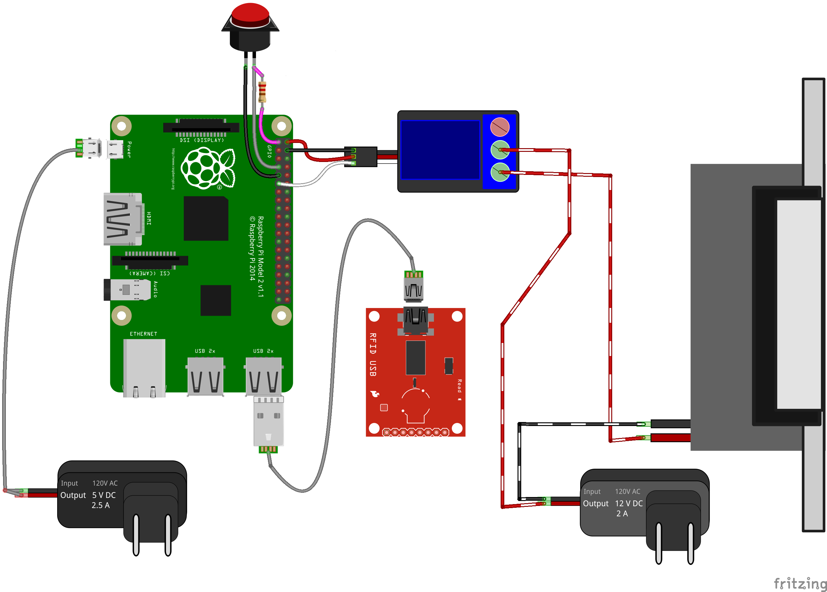
The system consists of a cheap USB RFID reader connected to the Raspberry Pi over its USB cable, and a 12V relay board that delivers power to an electric strike when triggered by the Raspberry Pi's GPIO pins, as shown below.
Picking out an RFID reader
One of the obstacles I faced when building this is the apparent immaturity of the DIY RFID market. As of when I'm writing this in 2019, RFID readers come in three forms, if we discount hand-held readers and other devices that don't fit our use case.
The first is as an antenna and board from the conventional DIY sellers. SparkFun has a couple of RFID antennas and compatible RFID boards. Adafruit has an RFID shield for Arduino, and an assembled RFID reader with a PS/2 Interface. These are all cost around $40 at least and require some technical knowledge to set up.
The second category includes ultra-premium products from RFID-focused engineering firms such as the Thingmagic Elara USB RFID reader from AtlasRFIDstore.com. It's $475.
The last category consists of dozens and dozens of identical, cheap, Chinese electronics sold through Amazon, NewEgg, AliBaba, and the like. If you search for an RFID reader on any of these or just Google, you'll see dozens of the little black boxes you see below for anywhere from $5 to $20. It's a ready-to-use solution at a very low price, so this is what I recommend.
I try to void shopping at Amazon and others exploitative marketplaces, but I don't know of a reputable source for these low-cost Chinese RFID readers, so I went with NewEgg. Suggestions for better sources are welcomed.
Choosing your frequency
This question wasn't well addressed in the tutorials I used, and most guides on this are confusing. What I found, however, is that there are two dominant standards for basic applications: 125kHz and 13.56MHz. There are many others for advanced applications such as active RFID technology like that used in a car's remote keychain fob, but if you're looking to unlock a door, just get one of these. The cheap, questionably manufactured products I suggested come in either one. I suggest 13.56MHz. I used 125kHz because that was what I initally bought, and the two seem functionally identical, but 13.56 seems slightly more common and thus easier to buy tags for. The rest of this guide should apply regardless of which option you take, just be aware that all your RFID tags and all your RFID readers will need to match. You can also get writable tags to store information, but I just went with permanent tags bearing a simple ID number. Maybe writable would be cool on a future project, but I don't see a need for it on this one.
Setting up the RFID readerTo start, connect your RFID reader over USB to a computer running Windows. Its power light will illuminate, and if you swipe a tag over it, the reader will beep and the light will blink once. If you open notepad and swipe, you'll see the tag's code appear. This is because these USB RFID readers emulate a keyboard. They read the RFID number, and then they output it as ASCII characters sequentially.
Next, set up your Raspberry Pi with the latest version of Raspbian OS and create a directory to work in. Create a text file to contain the list of users and their IDs and copy over the test code supplied to get started. The Python script requires root privileges in order to read signals from the RFID reader that is plugged in over USB, so run the script using the "sudo" prefix.
When run, the script should continuously monitor the RFID reader. When a code is found, it will check if it is on the list of approved codes and either report the name of the associated user or report that the code wasn't found on the list.
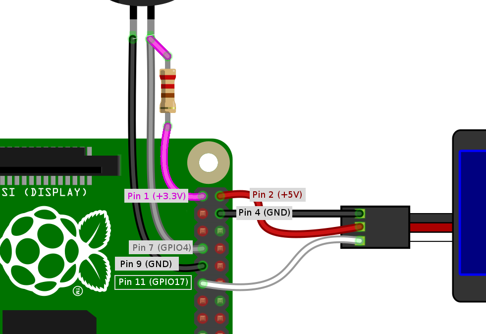
Setting up the relaySince you should already have the RFID reader working at this point, I recommend connecting the relay board to the Pi as seen in the diagram below. The power and ground connections can be made to any 5V and GND pins, however I used Pin 2 for my 5V pin and Pin 4 for my ground. I used Pin 11 (GPIO17) for my signal. Be sure to change this in the python script if you use a different signal pin.
Now, when you swipe a tag, if it is approved then the relay board should activate for 3 seconds, illuminating an LED and making an audible click before shutting off.
Setting up the electric strikeTest the strike by connecting it to the 12V power supply. You can add a barrel jack connector if you wish, however I just cut the connector off the power supply and stripped the wires. Check the power supply to determine which wire is the positive and which is ground, then connect the wires to the electric strike in a temporary fashion with alligator clips. You can plug in the power supply or turn on a surge protector into which it's plugged, and the strike should make a faint buzzing and the gate should transition from fixed to movable.
Depending on your model, your electric strike may have two wires or four. The strike I found has four, because it was designed to be compatible with either a 12V or 24V power supply. In the datasheet, it had a hookup guide for each, so I made the necessary connections for 12V.
Once you're confident that it works, solder the ground wire of the power supply to the ground wire of the strike or connect them permanently by other means. Connect the positive lead to the center connector of the relay, which is the common connector. It should be labeled "COM". Then connect the positive connection of the strike to the normally closed gate of the relay. It should be labeled "NC", as opposed to the normally open gate which is labeled "NO".
Most of the work is now done. If the Raspberry Pi is on and the 12V AC-DC converter is plugged in, then run the python script that reads the RFID reader (as a root user, as before). Now, swiping an approved RFID tag over the RFID reader should activate the relay as it did earlier, but it should power up the door strike when it does, allowing the door to open.
Setting up the script to run on bootDepending on your needs, you could call this done, but there are at least two things you'll still probably want to do. First, you'll want to set up a means of tracking who badges in, and second, you'll want to set the system to start up automatically when the Pi is plugged in. Otherwise, if there is a power failure, the door lock will remain off until it's manually reset.
Instructions for setting up a python script to run at startup were found on this page by Dexter Industries. Edit the file "/etc/rc.local" in Nano, as root user:
sudo nano /etc/rc.localAdd the command to start the program, using its full path name.
sudo python /home/YOUR_DIRECTORY_PATH/sample.py &Include the ampersand at the end to instruct it to run in the background, and make sure that the final line of the text file remains "exit 0" as it was originally (without the quotes, obviously).
Reboot to test. The python script should run immediately upon startup.
Tracking RFID swipe eventsIf you want to be able to see who has used the door and at what time, you can do so by reviewing the log file. The log file is appended with the time, ID number, and associated user each time a badge is checked by the python script. But you'll likely want to be able to read the file without using SSH to access the Raspberry Pi. To do this, we'll need to set up an automated process to copy the log file to a cloud storage drive every time a badge swipe event occurs. To do this, I recommend using Rclone.
To use Rclone, you'll first need to get API keys for a Google Drive folder. This process is best described in a post on Medium by Annis Souames: "How To Upload Files Automatically To Drive with Python". His guide walks through the process of setting up a file sync using the PyDrive python library. You might want to try completing his tutorial and see if it works for you. I used Rclone because I couldn't get Python to recognize a PyDrive command, but if works for you, great.
If it doesn't, then just make sure you generated the API keys that Annis walks you through generating on the Google Developer console. There are a lot of buttons, but if you follow his instructions, it should work.
Rclone
Once you have your API keys, run
sudo rclone configIf you run this without sudo, it will appear to work fine, but then when you try to run the rclone commands in the python script, it will fail because the python script runs as the root user.
The rclone config command will generate and save an rclone configuration profile. I found that If it isn't generated with root privileges, then your python script won't find it since it runs as root user.
Run through the configuration process exactly as it's described in the rclone documentation for setting up a Google Drive sync.
When you're done, try the test commands. Log in to the associated Google Drive account and check to see if the file uploaded it. Now, uncomment the lines which run rclone after every badge swipe. This will copy over the log file to Google Drive.
I recommend making a dedicated Google account for this project that is different from your personal Google Drive account, and then sharing the folder in which the log file gets copied with your regular account. The reason for this is that rclone is powerful, and has the ability to delete or overwrite any files on your Google Drive. In the case of an accident or some kind of hack, Rclone could theoretically be used to steal or ransom data in the associated cloud storage location it's attached to. I use my Google Drive to store sensitive information, so I took this step to wall off the log-file sync process from my valuable cloud storage space.
Going further, Part I: door switchOnce the reader worked, I connected a magnetic door sensor to the Raspberry Pi as well, which reads when the door state changes from opened to closed or vice-versa and logs this in the log file as well. It's represented in the diagram as a button, as it works the same way: when the door is closed, the circuit is closed, and when it's open, so is the circuit. It needs a pull-up resistor, which I connected to the first pin of the Pi, which delivers a constant 3V.
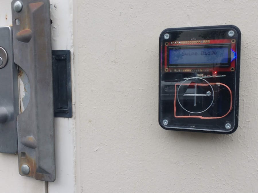
The LCD allows the Pi to provide a user with feedback. It turns out this makes a huge difference to user experience: people avoided using the system because it was opaque and lacked clear feedback. The LCD allows the Pi to declare "ACCESS GRANTED" followed by the username, which people seem to like.
Circuit Basics has a great guide on connecting the LCD to the Pi. I connected the following pins:
- LCD 1 (GND) to Pi 39 (GND)
- LCD 2 (VCC) to Pi 4 (5V)
- LCD 3 (V0) to a 2 kOhm resistor, then to GND
- LCD 4 (RS) to Pi 37 (GPIO26)
- LCD 5 (R/W) to GND
- LCD 6 (E) to Pi 35 (GPIO19)
- LCD 7,8,9,10: Unused
- LCD 11 (D4) to Pi 33 (GPIO13)
- LCD 12 (D5) to Pi 31 (GPIO6)
- LCD 13 (D6) to Pi 29 (GPIO5)
- LCD 14 (D7) Pi 23 (GPIO11)
- LCD 15 (K) to GND
- LCD 16 (A-Red) to a 330 Ohm resistor to Pi 11 (GPIO17)
- LCD 17 (A-Green) to a 330 Ohm resistor to Pi 27 (GPIO13)
- LCD 18 (A-Blue) to a 330 Ohm resistor to Pi 22 (GPIO15)
Most conventional LCDs have a single LED backlight, but this one has three in different colors, which allows the Pi to change the LCD background color along with the text. I really like the effect, because it sits on blue during normal use, but turns green when access is granted and red when access is denied.
Going further, Part III: Door bellLike many industrial facilities, our makerspace gets loud, making a knock on the door inaudible. A button alerts those inside when someone without access is requesting to be let in. The button operates the same way as the door switch. One end is connected to the shared GND connections the LCD uses to reduce the number of wires passing through a small hole in the wall. The other end connects to Pi pin 12 (GPIO18). It is also pulled high by a pull-up resistor connected to pin 1. The Pi can then activate a buzzer using another relay or activate sound through its audio jack, or send a notification over SMS text message, or a number of other options.


Comments
Please log in or sign up to comment.