This project has been planned thinking in the Exploring & Understanding Our Connected World contest. And its development depends on the hardware contest, since for a prototype I would need two wifi boards, but I only have 1 ESP32.
The main goal of this project is to show a simplified version of what would be a real real-time, global connected, situation awareness. It is based on the idea of a connected mesh around vehicles and road elements (traffic lights, traffic sign, ...). In the future, with the increasing of the autonomous vehicles and the improvement of the algorithms, would not be crazy that every car on the road to be self-driven. Even in the case, that there were only connected vehicles (but not self-driven), the communication among them would increase the security on the road, notifying the driver about the upcoming events before reaching them. This will allow the driver (human or algorithm) to adapt seamlessly.
The prototype
The prototype is a very simplified version of a situation where a car is driving along a highway and receive, from the connected mesh, the information about a crash in the upcoming turn. After that the car will reduce speed until it get to the crash site.
Also, the second part of the prototype would be adding a sensor to the car so it can also trigger some event into the network. The trigger will be some easy event, like detect a black paint in the floor with some line-follower sensor.
This two scenarios covers the implementation of a comunication in both ways from and to the network. The nodes would be some battery-driven boards, this is why I think the proton family would be an ideal choice as the main board of each node in the mesh ( cars, signs, poles, ...)
The beginning
The main part of this project is the car, driven by the Argon module, that sends and receives the signals. So, it seems that is the first part that we should mount. Also, in this part I will learn how the Particle environment works, and how to start programming in the Cloud IDE.
For the chassis and motors I get a 2WD starter kit (Link) and a L298N controller (Link). This kit is easy to build, and using the regulator embedded in the L298N controller, I can power all the car with a 2S LiPo battery. Also, the interface to control the L298N is very easy, since with just 4 PWM signals, we can control the movement and speed of the motors.
Also, since our project consist in detecting objects and trigger events in the mesh, we also need something to sense the environment. In our prototype, we are using an ultrasound sensor.
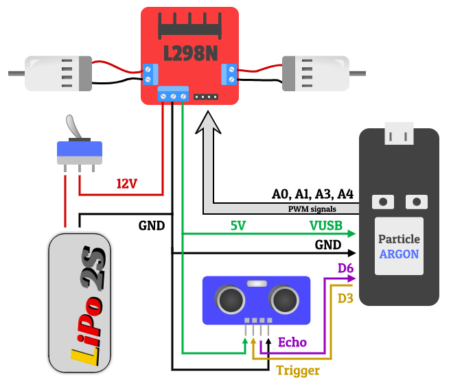
The connection of all the components of the project can be seen in the following image.
In order to program the Particle Argon, we need to use the Particle IDE, an online development IDE, that allows you to flash the firmware On The Air, without physically connecting the module to the PC.
The main function of the software is to move the car and emit and receive signals. There will be two types of allowed movement: one is the route mode, and the other one is the simple mode. In route mode, the car shall move using a predefined directives while in the simple mode, the car just move according to a command.
No matter the current mode of the car, if it senses an obstacle, it shall stop and emit an event. This is the part that simulate a crash in a highway, or any kind of problem on the way. Also, the car shall receive all the events relative to its area, so in case of an slow-down event, it shall reduce its speed.
I am dividing the code in three main parts:
- The CarController which controls the output of the Argon to control the motors.
- The SensorUltrasound which "talks" to the hc-sr04 and get the readings of the distance.
- Lastly the MainLoop where all the parts are connected among them, and with the cloud.
The CArController class is in charge of knowing how to move the car, which signals have to be generated in order to move in an specific manner. The basic interface would be as follows (All the code is in github, this is a simplified version):
class CarController{private:

  // Route mode  struct Waypoint wp_list[10]; // 10 waypoints  int wp_list_num; // Number of used waypoints
 int maxSpeed; // Maximum speed
 int pins[2][2]; // Pins where the L298N is connected
 enum DIRECTION currDirection; // Stores the current direction of movement.
 enum MODE modo; // Mode of moving: route or simple
public:    CarController(int right_pin1, int right_pin2, int left_pin1, int left_pin2);    ~CarController(){};    // Initialize all the necessary hardware and software.  void Init();    // Moves the car accordingly (this function shall be called every few main loops  void Move();

  // Set max speed
  void setMaxSpeed();
};
With this interface, we want to call the Move function every main loop. This function will update the output of the PWM signals to follow the current mode and direction. Also, the maxSpeed variable is used to control how fast the car would move. This variable is changed when an event is received.
In order to move the motors, the CarController has to generate a PWM signal. A PWM signal, is an square wave signal where the width of the "high" and "low" side of the signal can be adjusted. This allows one to control the speed of the motors. This can be done with an analogWrite on a digital output pin. With a value of 255 the pin is always "high" and is like there is no PWM, with 125 the PWM is half of the time high, the other half low.
For example, in order to generate a PWM signal at 50% of duty cycle ( 50% time high, 50% low), the following code can be used.
// setup
pinMode(A1, OUTPUT);

//loop
int maxFreq = analogWriteMaxFrequency(A1);
analogWrite(A1, 125, maxFreq / 2);
This class if the communication interface with the hc-sr04. This class is very simple, since it only has two methods: one for the initialization and one for the measure. The sensor need two pins, one for the trigger and one for the echo. This device sends an ultrasound wave towards, and then receive it after it bounces in an object.
Then, the device measure the time between the two pulses, and from that time, and knowing the speed of sound, we can measure the distance traveled by the wave,and then the distance. The formula to calculate the distance is:
distance = time (us) * 0.034/2
In order to do the math and activate the trigger for the sensor, I created a class, itsinterface would be:
class UltraSoundSensor{private:
 int triggerPin; int echoPin;    // Last measured time  unsigned long echotime;   public:    UltraSoundSensor(int trigger, int echo);    ~UltraSoundSensor(){};    void Init();    float Measure();};
The tricky part about this sensor and the Argon, is that the Argon works on 3.3V while the hc-sr04 work on 5V logic. That means that when the Argon send a pulse of 3.3V into the trigger pin, all work nice since the 3.3V is inside the specs of the sensor. However, when the sensor send back the data, the Argon cannot handle 5.0V, so we need to lower the voltage of the signal in the echo pin. In order to do it in an easy way, I soldered a tension divider as in this schematic.
The last, but not least part, is the main loop, which interconnects everything. We have to:
- Create and instantiate the classes CarController and SensorUltrasound
- Connect the Cloud variables and functions that we need
- Create the wrappers to talk to the classes.
First we create the clases, my code is based in the diagram that I show earlier, so I need to connect the CarController to A0,A1, A3,A4 pins, and the ultrasound sensor to the D3, D6. Also, I need to define some variables.
CarController Car( A4, A3, A0, A1);UltraSoundSensor Sensor(D3, D6);

unsigned long int lastTime;int periodMillis = 200;
Then in the setup we have to Initialize the classes and connect the cloud functions of the Particle environment:
void setup() {
   Car.Init();
   Sensor.Init();

   // Functions to handle the behavior of the car
   Particle.function("setDirection", pChangeDir);
   Particle.function("setMode", pSetMode);
   Particle.function("SensorTest", pSensorTest);
   Particle.function("Speed", pSetSpeed);

   // The event to slow down
   Particle.subscribe("cautionspeed", caution_speed_event, MY_DEVICES);
}
Then the main loop is really simple, we move the Car, chech for an obstacle, and wait for the next period.
void loop() {
   unsigned long elapsed;
   Car.Move();

   // IF we detect something we stop the car.
   if( Sensor.Measure() < 10.0f){
       Particle.publish("cautionspeed","70", PUBLIC);
       pSetMode("simple");
   }

   elapsed = millis() - lastTime;
   if ( elapsed < periodMillis )
       delay(periodMillis - elapsed);
}
And finally we create all the functions to handle the commands from the particle cloud.
void caution_speed_event(const char *event, const char *data){
   pSetSpeed(data);
}

int pChangeDir(String cmd){
   return Car.setDirection(cmd);
}
int pSetMode(String cmd){
   if( cmd == "route"){
       return Car.setModeRoute();
   }else if(cmd=="simple"){
       Car.setDirection("none");
       return Car.setModeSimple();
   }else{
       Car.setDirection("none");
       return Car.setModeSimple();
   }
}
int pSensorTest(String cmd){
   if( cmd == "dist" ){
       return int(Sensor.Measure());
   }
   return -1;
}
int pSetSpeed(String cmd){
   int value;
   value = cmd.toInt();

   if(value > 0 && value < 255){
       return Car.setMaxSpeed(value);
   }
   return -1;
}
As a result we have a car that can move in a route mode and in simple mode. And when he receives an event, it updates its speed. Here is a small video of the car finding an obstacle. I hope you enjoy!


_1PrVp5RTYf.png?auto=compress%2Cformat&w=900&h=675&fit=min)
_zhWsCcSEcl.jpg?auto=compress%2Cformat&w=48&h=48&fit=fill&bg=ffffff)


Comments
Please log in or sign up to comment.