Hardware components | ||||||
| × | 1 | ||||
| × | 1 | ||||
![]() |
| × | 1 | |||
![]() |
| × | 4 | |||
![]() |
| × | 1 | |||
![]() |
| × | 1 | |||
| × | 1 | ||||
Software apps and online services | ||||||
![]() |
| |||||
| ||||||
![]() |
| |||||
Hand tools and fabrication machines | ||||||
![]() |
| |||||
![]() |
| |||||
![]() |
| |||||
![]() |
|
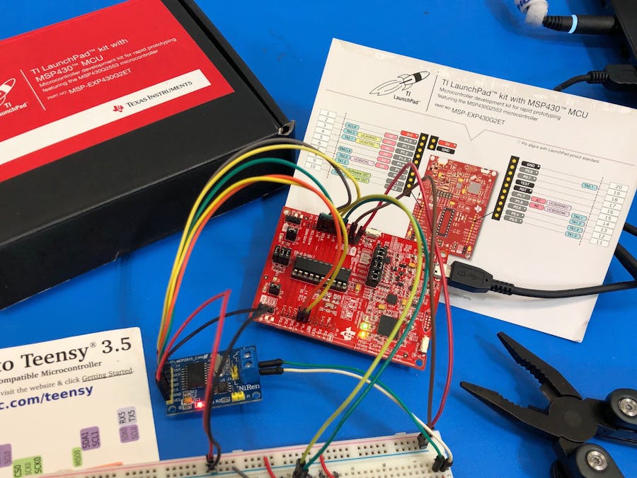
What is the DIM?The Driver Input Module (DIM) is a Texas Instruments MSP430-G2553 Microcontroller with the requirements of handling driver input of Lithium, UC Irvine’s 2019 FSAE Electric Racecar competing in Lincoln, Nebraska. The driver input sensors includes two independent Accelerator Pedal Position Sensors (APPS), one Brake System Encoder (BSE), and one Steering Angle Position Sensor (SAPS) and a drive button. These inputs are processed by the DIM then broadcasted to the Racecar's CAN-Bus (Controller Area Network) to interface with other control modules.
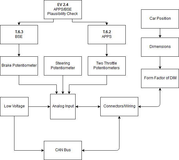
Context of the DIM:The figure below describes the context of the DIM. The driver input sensors (APPS, BSE, and SAPS) are analog potentiometers connected to the Analog-to-Digital Converter (ADC) of the DIM. The DIM utilizes this input data to check for faults in the system; if no faults occur, these values are transmitted to other control modules of the racecar via CAN. Since the MSP430 microcontroller has no native CAN support, a NiRen SPI-CAN controller is connected via Serial Peripheral Interface (SPI) to interface DIM to the Racecar's CAN-Bus.
Description of the Faults:“Faults” were previously mentioned and are critical to the design of the DIM for a tech-ready racecar. Faults can arise if the accelerator (depressed at >20%) and brake pedal are actuated at the same time, if a sensor is disconnected, or if either APPS sensors output different voltages. These faults are defined as a “plausibility” by the FSAE rulebook, and must be accounted for in our Failure Mode Effect Analysis (FMEA). If a plausibility occurs, the DIM will send throttle values of zero until the fault is cleared.
Why is DIM important?DIM has two important tasks: the first task is enable operation of the racecar after the tractive system is closed, and the second to detect faults to prevent the Racecar from transmitting incorrect pedal values for safe operation.
Working on the DIM provides hands-on experience with the Texas Instruments MSP430 series microcontroller and interfacing it with CAN Bus to integrate it in a safe racecar for UC Irvine. DIM has been in development since October 2018 quarter and will be integrated on our FSAE Electric Racecar for the 2019 season.
CurrentStatus: DIM is currently being mounted on our custom interface PCB and tested for our initial release, Version 1.0. The .Brd (EAGLE CAD) and Bill of Material files attached to this Project have gone through 8 internal revisions and are labeled "V1.8"; these internal revisions refer to our public release Version 1.0. We included the .Brd, .Schematic, and a Bill of Materials for advanced users to evaluate our integrated component. Intermediate users may refer to the breadboard diagrams.
The next version will not use the full LaunchPad and will be labeled Version2.0. This next version will use an interface board for the DIP packaging of the MSP430, MCP2515, and TJA1050 ICs.
A prospective Version3.0 will use a Texas Instruments CAN Controller and Transceiver.
April2019
*****************************************************************************************************FurtherReadings:
Sparkfun - Analog-to-Digital Conversion Introduction
https://learn.sparkfun.com/tutorials/analog-to-digital-conversion/all
CSS Electronics - Simple Intro to Controller Area Network Bus
https://www.csselectronics.com/screen/page/simple-intro-to-can-bus/language/en
Texas Instruments - Introduction to the Controller Area Network
http://www.ti.com/lit/an/sloa101b/sloa101b.pdf
Anteater Electric Racing - Simple Introduction to EAGLE CAD
https://drive.google.com/open?id=1jNvfpGzudJc0RT9-VRTbLf6C7m-Ko0kh
Anteater Electric Racing - Coupling Capacitor Explanation (for PCB)
https://drive.google.com/open?id=1bQqdNWBqOYyQLjGkDOjo-0sJ0xrkmafCE3i5SI-hUdg
*****************************************************************************************************Updates:
V0.2 - April 14, 2019:
*Moved this project to our Engineering Race Team account.
*Removed PWM timer for motor control as we use a different control module for this operation.
*Added CANbus functionality via SPI, to interface with other control modules of the vehicle (for Torque Vectoring and Data Logging).
V0.1 - February 2019
*Initial version with PWM output (Please ask for PWM files).
*Working ADC and UART for debug.*No working CANBus output.
*****************************************************************************************************To-DoList:
*Calibrate sensors for proper fault detection once integrated.
*Publish CAN protocol for implementation on any Racecar with electronic throttle.
VERSION 1.0 (current):
*Test CANBus broadcast on a CAN-Analyser tool.
*Test CANBus broadcast for other control modules.
*Mount DIM on interface PCB.*Test DIM on PCB.
VERSION 2.0:
*Breadboard test of MSP430G2553 (DIP Package) on with MSP2515 CAN Controller (DIP) and TJA1050 (DIP).
*Embed DIP Packaging on custom PCB.
*Test second version on Racecar.
VERSION3.0:
*Implement Version 2.0 with a Texas Instruments CAN Controller and Transceiver.
//##########################################################################################################################################################
// Anteater Electric Racing "Driver Input Module"
//
// Engineer: Lucas Juttner
// Date: 4/23/2019
// School: University of California, Irvine
//
// Description: Program takes in analog input from four potentiometers
// (two from accelerator pedal, one from brake pedal, and one from steering column)
// Analog input values are sent over CANBus along with a "ready" flag
// and a "fault" flag. "Ready" flag is set when brake pedal is pressed
// at the same time as start button. "Fault" flag is described in rule T.6.2 in the
// FSAE 2019 rulebook.
//
//##########################################################################################################################################################
#include <ADC.h>
#include <Faults.h>
#include <msp430g2553.h>
#include <PWM.h>
#include <SPI.h>
#include <stdint.h>
#include <UART.h>
#include <mcp2515.h>
//############################################### Global Variable initializations ##########################################################################
can_t can_tx; //CAN transfer struct
can_t can_rx; //CAN receive struct
int startButton = 0; //start button flag
int CAN_Data[5];
char ready= 0x00;
char fault = 0x00;
//############################################### Start of main function ###################################################################################
int main(void)
{
WDTCTL = WDTPW | WDTHOLD; // stop watchdog timer
BCSCTL1 = CALBC1_8MHZ; // Set range
DCOCTL = CALDCO_8MHZ;
init_ADC();
// init_UART();
// init_PWM();
P1DIR |= BIT0; // P1.0 Green LED
//----------------------------------------------- Configure P1.4 as interrupt pin --------------------------------------------------------------------------
P1OUT |= BIT4;
P1REN |= BIT4;
P1IE |= BIT4; // P1.4 Interrupt Enable
P1IES |= BIT4; // P1.4 Interrupt on Hi/lo Edge
P1IFG &= ~BIT4;
//----------------------------------------------- Configure P2.1 as digital input for start button------------------------------------------------------
P2SEL &= ~BIT1;
P2DIR &= ~BIT1;
P2IN &= ~BIT1;
P2REN = BIT1;
//----------------------------------------------- Initiate SPI and CAN structs --------------------------------------------------------------------------
init_MCP2515_SPI();
MCP2515_init();
init_MCP2515_CANVariable(&can_tx);
init_MCP2515_CANVariable(&can_rx);
__enable_interrupt();
//----------------------------------------------- Beginning of primary while loop --------------------------------------------------------------------------
while(1){
read_ADC(); //Call function to read analog to digital input values
if(P2IN & BIT1){ //If input is high on P2.1,
startButton = 1; //set startButton flag to high(1)
}
if((brakeInput >> 2) > 0x0F && startButton==1){ //If brake is pressed, and start button is on,
ready = 0xFF; //set "ready" flag to high(0xFF)
while (1) { //Enter new while loop that will continue until reset
read_ADC(); //Call function to read analog to digital input values
// if(APPS_Fault(acc1Input,acc2Input)){ //If fault occurs, set "fault" flag to high(0xFF)
// fault = 0xFF;
// }
CAN_Data[0] = steeringInput >> 2; //Fill CAN data buffer with appropriate data values
CAN_Data[1] = brakeInput >> 2;
CAN_Data[2] = acc1Input >> 2;
CAN_Data[3] = ready;
CAN_Data[4] = fault;
if(MCP2515_spi_test ()){ //Validate SPI communication functions properly
P1OUT ^= 0; // P1.0 toggle
}
}
}
else{ //If start sequence isn't initiated, send CAN data regardlesss
CAN_Data[0] = steeringInput >> 2;
CAN_Data[1] = brakeInput >> 2;
CAN_Data[2] = acc1Input >> 2;
CAN_Data[3] = ready;
CAN_Data[4] = fault;
if(MCP2515_spi_test ()){
P1OUT ^= 0; // P1.0 Toggle
}
}
}
}
//############################################### Port1: Interrupt-Service-Routine ###################################################################################
#pragma vector=PORT1_VECTOR
__interrupt void Port_1(void)
{
MCP2515_can_rx0(&can_rx); // Read information in RX0
int i;
for(i = 0; i < 5; i++){
can_tx.data[i] = CAN_Data[i];
}
MCP2515_can_tx0(&can_tx); // Send CAN message
P1IFG &= ~BIT4; // P1.4 IFG reset interrupt
}
//##########################################################################################################################################################
// Anteater Electric Racing "Driver Input Module"
//
// Engineer: Lucas Juttner
// Date: 4/23/2019
// School: University of California, Irvine
// File: ADC.c
//
// Description: Functions initialize Analog to Digital Converter and place input values into adc buffer
//
//##########################################################################################################################################################
#include <ADC.h>
#include <msp430g2553.h>
//----------------------------------------------- Function to Initialize ADC ------------------------------------------------------
void init_ADC(){
ADC10CTL1 = INCH_3 + CONSEQ_1; //Channel 3 down to 0 and sets up single channel conversion
ADC10CTL0 = ADC10SHT_2 + MSC + ADC10ON + ADC10IE;
ADC10DTC1 = 4;
ADC10AE0 = BIT3 + BIT2 + BIT1 + BIT0; //enables analog on pin 1.0, 1.1, 1.2, and 1.3
}
//----------------------------------------------- Function to Read Values from ADC------------------------------------------------------
void read_ADC(){
ADC10CTL0 &= ~ENC; //Enable ADC
while(ADC10CTL1 & BUSY); //Wait while converting
ADC10SA = (unsigned int)adc; //Put values from register into adc buffer
ADC10CTL0 |= ENC + ADC10SC;
__bis_SR_register(CPUOFF + GIE);
steeringInput = adc[0]; //Set variables to specific locations in adc buffer
brakeInput = adc[1];
acc1Input = adc[2];
acc2Input = adc[3];
}
//############################################### ADC10: Interrupt-Service-Routine ###################################################################################
// ADC10 interrupt service routine
#if defined(__TI_COMPILER_VERSION__) || defined(__IAR_SYSTEMS_ICC__)
#pragma vector=ADC10_VECTOR
__interrupt void ADC10_ISR(void)
#elif defined(__GNUC__)
void __attribute__ ((interrupt(ADC10_VECTOR))) ADC10_ISR (void)
#else
#error Compiler not supported!
#endif
{
__bic_SR_register_on_exit(CPUOFF); // Clear CPUOFF bit from 0(SR)
}
//##########################################################################################################################################################
// Anteater Electric Racing "Driver Input Module"
//
// Engineer: Lucas Juttner
// Date: 4/23/2019
// School: University of California, Irvine
// File: ADC.h
//
// Description: Functions initialize Analog to Digital Converter and place input values into adc buffer
//
//##########################################################################################################################################################
unsigned int adc[4];
int acc1Input;
int acc2Input;
int brakeInput;
int steeringInput;
void init_ADC();
void read_ADC();
__interrupt void ADC10_ISR(void);
//##########################################################################################################################################################
// Anteater Electric Racing "Driver Input Module"
//
// Engineer: Lucas Juttner
// Date: 4/23/2019
// School: University of California, Irvine
// File: SPI.c
//
// Description: Functions that initialize SPI communication, and provide all functions needed for CAN Communication
//
// Special thanks to ElectroDummies and K. Evangelos for their tutorial and sample code for CAN communication
// Their tutorial can be found here: http://www.electrodummies.net/en/msp430-2/msp430-can-interface/
//##########################################################################################################################################################
#include <SPI.h>
#include <msp430g2553.h>
#include <mcp2515.h>
#include <stdint.h>
#include <ADC.h>
//----------------------------------------------- Function to Initialize SPI ------------------------------------------------------
void init_MCP2515_SPI(){
P1SEL = BIT5 + BIT6 + BIT7; //1.5 is clock source, 1.6 SOMI, 1.7 SIMO
P1SEL2 = BIT5 + BIT6 + BIT7;
P2DIR |= BIT0;
P2OUT |= BIT0; //Set P2.0 as slave select pin
UCB0CTL1 |= UCSWRST; //USCI software reset (reset to begin initialization)
UCB0CTL0 |= UCCKPL + UCMSB + UCMST + UCMODE_0 + UCSYNC; //Most sig bit first, set as master, spi mode on
UCB0CTL1 |= UCSSEL_2; //Use SMCLK for clock source
UCB0BR0 |= 0X02; //Divide clock by 2
UCB0BR1 = 0;
UCB0CTL1 &= ~UCSWRST; //initialize USCI state machine
__delay_cycles(DELAY_100ms);
while(!(IFG2 & UCB0TXIFG));
UCB0TXBUF = 0x00; //Initialize transfer buffer at 0x00
}
//----------------------------------------------- Function to Transmit via SPI ------------------------------------------------------
unsigned char transmit_MCP2515_SPI(unsigned char value){
UCB0TXBUF = value;
while(UCB0STAT & UCBUSY);
return UCB0RXBUF;
}
//----------------------------------------------- Function to Reset MCP2515 chip ------------------------------------------------------
void MCP2515_reset(){
MCP2515_CS_LOW;
transmit_MCP2515_SPI(MCP2515_RESET);
MCP2515_CS_HIGH;
__delay_cycles(DELAY_100us);
}
//----------------------------------------------- Function to Initialize CAN Structs------------------------------------------------------
void init_MCP2515_CANVariable(can_t * can){
can -> COB_ID = 0x001;
can -> status = 0x01;
can -> dlc = CAN_DLC;
can -> rtr = CAN_RTR;
can -> ext = CAN_EXTENDET;
// can -> data[0] = 0x69;
char i;
for(i = 0; i < CAN_DLC; i++){
can -> data[i] = 0x05;
}
}
//----------------------------------------------- Function to Write to MCP2515 chip ------------------------------------------------------
void write_MCP2515(uint8_t addr, uint8_t data){
MCP2515_CS_LOW;
transmit_MCP2515_SPI(MCP2515_WRITE);
transmit_MCP2515_SPI(addr);
transmit_MCP2515_SPI(data);
MCP2515_CS_HIGH;
// __delay_cycles(DELAY_100us);
__delay_cycles(DELAY_1ms);
}
//------------------------------------- Function to Write to multiple registers of MCP2515 chip ----------------------------------------------
void write_many_registers_MCP2515(uint8_t addr, uint8_t len, uint8_t *data){
MCP2515_CS_LOW;
transmit_MCP2515_SPI(MCP2515_WRITE);
transmit_MCP2515_SPI(addr);
char i;
for(i = 0; i < len; i++)
{
transmit_MCP2515_SPI(*data);
data++;
}
MCP2515_CS_HIGH;
__delay_cycles(DELAY_100us);
}
//----------------------------------------------- Function to Read from MCP2515 chip ------------------------------------------------------
uint8_t read_MCP2515(uint8_t addr){
uint8_t data;
transmit_MCP2515_SPI(MCP2515_READ);
transmit_MCP2515_SPI(addr);
data = transmit_MCP2515_SPI(MCP2515_DUMMY);
MCP2515_CS_HIGH;
__delay_cycles(DELAY_100us);
return data;
}
//----------------------------------------------- Function to Read from multiple registers of MCP2515 chip---------------------------------------------
void read_many_registers_MCP2515(uint8_t addr, uint8_t length, uint8_t *data){
MCP2515_CS_LOW;
transmit_MCP2515_SPI(MCP2515_WRITE);
transmit_MCP2515_SPI(addr);
char i;
for(i = 1; i < length; i++){
*data = transmit_MCP2515_SPI(MCP2515_DUMMY);
data++;
}
MCP2515_CS_HIGH;
__delay_cycles(DELAY_100us);
}
//----------------------------------------------- Function to Write CAN ID to MCP2515 chip ------------------------------------------------------
void write_id_MCP2515(uint8_t addr, BOOL ext, unsigned long id){
uint16_t canid;
uint8_t tbufdata[4];
canid = (unsigned short)(id & 0x0ffff);
if(ext == TRUE){
tbufdata[MCP2515_EID0] = (uint8_t) (canid & 0xff);
tbufdata[MCP2515_EID8] = (uint8_t) (canid / 256);
canid = (uint16_t)(id / 0x10000);
tbufdata[MCP2515_SIDL] = (uint8_t) (canid & 0x03);
tbufdata[MCP2515_SIDL] += (uint8_t)((canid & 0x1c)*8);
tbufdata[MCP2515_SIDL] |= MCP2515_TXBnSIDL_EXIDE;
tbufdata[MCP2515_SIDH] = (uint8_t)(canid / 32);
}
else // Sonst hier auch genutzt Standart 11-Bit-Identifier (CAN 2.0A)
{
tbufdata[MCP2515_SIDH] = (uint8_t)(canid / 8);
tbufdata[MCP2515_SIDL] = (uint8_t)((canid & 0x07)*32);
tbufdata[MCP2515_EID0] = 0;
tbufdata[MCP2515_EID8] = 0;
} // else
if(tbufdata[0] == 0xff) return;
write_many_registers_MCP2515(addr, 4, tbufdata);
__delay_cycles(DELAY_100us);
}
//----------------------------------------------- Function to Read ID from MCP2515 chip ------------------------------------------------------
void read_id_MCP2515(uint8_t addr, unsigned long* id){
uint16_t ID_Low, ID_High;
if(addr == MCP2515_RXB0SIDL)
{
ID_Low = (read_MCP2515(MCP2515_RXB0SIDL) >> 5);
ID_High = (read_MCP2515(MCP2515_RXB0SIDH) << 3);
*id = (unsigned long)ID_Low | (unsigned long)ID_High;
}
else
{
ID_Low = (read_MCP2515(MCP2515_RXB1SIDL) >> 5);
ID_High = (read_MCP2515(MCP2515_RXB1SIDH) << 3);
*id = (unsigned long)ID_Low | (unsigned long)ID_High;
}
}
//----------------------------------------------- Function to Initialize MCP2515 chip ------------------------------------------------------
void MCP2515_init(void){
MCP2515_reset (); // Reset MCP2515
__delay_cycles(DELAY_10ms); // Allow to reset
write_MCP2515(MCP2515_CANCTRL, 0x88); //Set CAN Control register to configuration mode
write_MCP2515(MCP2515_CANINTE, 0x03); //Set CAN to enable interrupts
write_MCP2515(MCP2515_TXB0CTRL, 0x03); //Set high message priority in transfer control register
write_MCP2515(MCP2515_CNF1,0x00); //Sets 125kb/s transfer speed using 4MHz SPI clock
write_MCP2515(MCP2515_CNF2,0xb9);
write_MCP2515(MCP2515_CNF3,0x05);
write_MCP2515(MCP2515_RXB0CTRL, 0x64); //Receive Buffer 0 Control - receive all messages
write_MCP2515(MCP2515_RXB1CTRL, 0x60); //Receive Buffer 1 Control - receive all messages
write_MCP2515(MCP2515_BFPCTRL, 0x00); //Disable RxnBF pins
write_MCP2515(MCP2515_TXRTSCTRL , 0x00); //Disable RTS pins
write_MCP2515(MCP2515_CANCTRL, 0x00);
}
//----------------------------------------------- Function to Modify single bit in register ------------------------------------------------------
void bit_modify_MCP2515(uint8_t addr, uint8_t mask, uint8_t data){
MCP2515_CS_LOW;
transmit_MCP2515_SPI(MCP2515_BIT_MODIFY);
transmit_MCP2515_SPI(addr);
transmit_MCP2515_SPI(mask);
transmit_MCP2515_SPI(data);
MCP2515_CS_HIGH;
__delay_cycles(DELAY_100us);
}
//----------------------------------------------- Functions to Send CAN data ------------------------------------------------------
void MCP2515_can_tx0(can_t *can){
if(can->dlc > 8) can->dlc = 8;
write_id_MCP2515(MCP2515_TXB0SIDH, can->ext, can->COB_ID);
if (can->rtr == TRUE)
{
uint8_t befehl = can->dlc;
befehl = befehl | 0x40;
if(befehl == 0x03) return;
write_MCP2515(MCP2515_TXB0DLC, can->dlc | 0x40);
}
else
{
write_MCP2515(MCP2515_TXB0DLC, can->dlc);
write_many_registers_MCP2515(MCP2515_TXB0D0, can->dlc, can->data);
write_MCP2515(MCP2515_TXB0CTRL, 0x0B);
}
}
void MCP2515_can_tx1(can_t *can){
if(can->dlc > 8) can->dlc = 8;
write_id_MCP2515(MCP2515_TXB1SIDH, can->ext, can->COB_ID);
if (can->rtr == TRUE)
{
uint8_t befehl = can->dlc;
befehl = befehl | 0x40;
if(befehl == 0x03) return;
write_MCP2515(MCP2515_TXB1DLC, can->dlc | 0x40);
}
else
{
write_MCP2515(MCP2515_TXB1DLC, can->dlc);
write_many_registers_MCP2515(MCP2515_TXB1D0, can->dlc, can->data);
write_MCP2515(MCP2515_TXB1CTRL, 0x0B);
}
}
void MCP2515_can_tx2(can_t *can){
if(can->dlc > 8) can->dlc = 8;
write_id_MCP2515(MCP2515_TXB2SIDH, can->ext, can->COB_ID);
if (can->rtr == TRUE)
{
uint8_t befehl = can->dlc;
befehl = befehl | 0x40;
if(befehl == 0x03) return;
write_MCP2515(MCP2515_TXB2DLC, can->dlc | 0x40);
}
else
{
write_MCP2515(MCP2515_TXB2DLC, can->dlc);
write_many_registers_MCP2515(MCP2515_TXB2D0, can->dlc, can->data);
write_MCP2515(MCP2515_TXB2CTRL, 0x0B);
}
}
//----------------------------------------------- Functions to Receive CAN data ------------------------------------------------------
void MCP2515_can_rx0(can_t *can){
read_id_MCP2515(MCP2515_RXB0SIDL, &can->COB_ID);
can->dlc = read_MCP2515(MCP2515_RXB0DLC);
char i;
for(i = 0; i < can->dlc; i++) can->data[i] = read_MCP2515(MCP2515_RXB0D0+i);
can->status = can->data[0];
MCP2515_clear_rx0();
MCP2515_int_clear();
__delay_cycles(DELAY_1ms);
}
void MCP2515_can_rx1(can_t *can){
read_id_MCP2515(MCP2515_RXB1SIDL, &can->COB_ID);
can->dlc = read_MCP2515(MCP2515_RXB1DLC);
char i;
for(i = 0; i < can->dlc; i++) can->data[i] = read_MCP2515(MCP2515_RXB1D0+i);
can->status = can->data[0];
MCP2515_clear_rx1();
MCP2515_int_clear();
__delay_cycles(DELAY_1ms);
}
//----------------------------------------------- Functions to Clear receive registers ------------------------------------------------------
void MCP2515_clear_rx0(void){
bit_modify_MCP2515(MCP2515_CANINTF, MCP2515_RX0IF, 0x00);
}
void MCP2515_clear_rx1(void){
bit_modify_MCP2515(MCP2515_CANINTF, MCP2515_RX1IF, 0x00);
}
void MCP2515_int_clear(void){
write_MCP2515(MCP2515_CANINTF, MCP2515_CANINTF_ALL_DISABLE);
}
//----------------------------------------------- Function to Test SPI communication ------------------------------------------------------
BOOL MCP2515_spi_test (void){
uint16_t data_rcv[11] = {0, 0, 0, 0, 0, 0, 0, 0, 0, 0, 0};
uint16_t data_snd[11]={0x88,0x03,0x90,0x02,0x05,0x02,0x3f,0x23,0x40,0x40,0x00}; //Data array
write_MCP2515(MCP2515_CANCTRL, data_snd[0]); //Transmit data from buffer to register, then read from register
data_rcv[0] = read_MCP2515(MCP2515_CANCTRL);
write_MCP2515(MCP2515_CNF1,data_snd[1]);
write_MCP2515(MCP2515_CNF2,data_snd[2]);
write_MCP2515(MCP2515_CNF3,data_snd[3]);
data_rcv[1] = read_MCP2515(MCP2515_CNF1);
data_rcv[2] = read_MCP2515(MCP2515_CNF2);
data_rcv[3] = read_MCP2515(MCP2515_CNF3);
write_MCP2515(MCP2515_RXM0SIDH, data_snd[4]);
write_MCP2515(MCP2515_RXM0SIDL, data_snd[5]);
data_rcv[4] = read_MCP2515(MCP2515_RXM0SIDH);
data_rcv[5] = read_MCP2515(MCP2515_RXM0SIDL);
write_MCP2515(MCP2515_CANINTE, data_snd[6]);
data_rcv[6] = read_MCP2515(MCP2515_CANINTE);
write_MCP2515(MCP2515_CANINTF, data_snd[7]);
data_rcv[7] = read_MCP2515(MCP2515_CANINTF);
write_MCP2515(MCP2515_TXB0SIDL, data_snd[8]);
data_rcv[8] = read_MCP2515(MCP2515_TXB0SIDL);
write_MCP2515(MCP2515_TXB1SIDL, data_snd[9]);
data_rcv[9] = read_MCP2515(MCP2515_TXB1SIDL);
write_MCP2515(MCP2515_CANCTRL, data_snd[10]);
data_rcv[10] = read_MCP2515(MCP2515_CANCTRL);
char i;
for(i = 0; i < 11; i++){
if(data_snd[i] != data_rcv[i]) return FALSE; // Check to see if receive buffer = transfer buffer
}
MCP2515_init();
return TRUE; //Return TRUE if SPI functions correctly
}
#include <stdint.h>
#include <mcp2515.h>
void init_MCP2515_SPI();
unsigned char transmit_MCP2515_SPI(unsigned char value);
void MCP2515_reset();
void init_MCP2515_CANVariable(can_t * can);
void write_MCP2515(uint8_t addr, uint8_t data);
void write_many_registers_MCP2515(uint8_t addr, uint8_t len, uint8_t *data);
uint8_t read_MCP2515(uint8_t addr);
void read_many_registers_MCP2515(uint8_t addr, uint8_t length, uint8_t *data);
void write_id_MCP2515(uint8_t addr, BOOL ext, unsigned long id);
void read_id_MCP2515(uint8_t addr, unsigned long* id);
void MCP2515_init(void);
void bit_modify_MCP2515(uint8_t addr, uint8_t mask, uint8_t data);
void MCP2515_can_tx0(can_t *can);
void MCP2515_can_tx1(can_t *can);
void MCP2515_can_tx2(can_t *can);
void MCP2515_can_rx0(can_t *can);
void MCP2515_can_rx1(can_t *can);
void MCP2515_clear_rx0(void);
void MCP2515_clear_rx1(void);
void MCP2515_int_clear(void);
BOOL MCP2515_spi_test (void);
//##########################################################################################################################################################
// Anteater Electric Racing "Driver Input Module"
//
// Engineer: Lucas Juttner
// Date: 4/23/2019
// School: University of California, Irvine
// File: mcp2515.h
//
// Description: Header/driver file with all register definitions for MCP2515 CAN Transceiver
//
// Special thanks to ElectroDummies and K. Evangelos for their tutorial and sample code for CAN communication
// Their tutorial and code can be found here: http://www.electrodummies.net/en/msp430-2/msp430-can-interface/
//##########################################################################################################################################################
#ifndef MCP2515_H
#define MCP2515_H
#include <msp430G2553.h>
#include <stdint.h>
//########################## General Definitions ###########################################################################################################
#define F_CPU 2000000 //Code to set delays, will have to change F_CPU value for different clock speeds
#define DELAY_1s F_CPU
#define DELAY_100ms (F_CPU / 10)
#define DELAY_10ms (F_CPU / 100)
#define DELAY_1ms (F_CPU / 1000)
#define DELAY_100us (F_CPU / 10000)
#define DELAY_10us (F_CPU / 100000)
#define DELAY_1us (F_CPU / 1000000)
#define BOOL char
#define TRUE 0
#define FALSE 1
#define CAN_RTR FALSE //Data Request = 1
#define CAN_DLC 5 //Number of bytes in the CAN message (maximum of 8)
#define CAN_EXTENDET FALSE //Only receive standard IDs DataRequest=1
#define MCP2515_CS_LOW P2OUT &=~ BIT0 //Set chip select variables
#define MCP2515_CS_HIGH P2OUT |= BIT0 //Set chip select variables
//############################# MCP2515 Commands ###################################################################################################################################
// -------------------------- Basic Commands --------------------------------------------------
#define MCP2515_WRITE 0x02
#define MCP2515_READ 0x03
#define MCP2515_READ_RX 0x90
#define MCP2515_WRITE_TX 0x40
#define MCP2515_DUMMY 0xFF
#define MCP2515_RESET 0xC0
#define MCP2515_BIT_MODIFY 0x05
#define MCP2515_READ_STATUS 0xA0
#define MCP2515_RX_STATUS 0xB0
#define MCP2515_RTS 0x80
// ------------------------------- Register Values -------------------------------------------------
#define MCP2515_RXF0SIDH 0x00
#define MCP2515_RXF0SIDL 0x01
#define MCP2515_RXF0EID8 0x02
#define MCP2515_RXF0EID0 0x03
#define MCP2515_RXF1SIDH 0x04
#define MCP2515_RXF1SIDL 0x05
#define MCP2515_RXF1EID8 0x06
#define MCP2515_RXF1EID0 0x07
#define MCP2515_RXF2SIDH 0x08
#define MCP2515_RXF2SIDL 0x09
#define MCP2515_RXF2EID8 0x0A
#define MCP2515_RXF2EID0 0x0B
#define MCP2515_BFPCTRL 0x0C
#define MCP2515_TXRTSCTRL 0x0D
#define MCP2515_CANSTAT 0x0E
#define MCP2515_CANCTRL 0x0F
#define MCP2515_RXF3SIDH 0x10
#define MCP2515_RXF3SIDL 0x11
#define MCP2515_RXF3EID8 0x12
#define MCP2515_RXF3EID0 0x13
#define MCP2515_RXF4SIDH 0x14
#define MCP2515_RXF4SIDL 0x15
#define MCP2515_RXF4EID8 0x16
#define MCP2515_RXF4EID0 0x17
#define MCP2515_RXF5SIDH 0x18
#define MCP2515_RXF5SIDL 0x19
#define MCP2515_RXF5EID8 0x1A
#define MCP2515_RXF5EID0 0x1B
#define MCP2515_TEC 0x1C
#define MCP2515_REC 0x1D
#define MCP2515_RXM0SIDH 0x20
#define MCP2515_RXM0SIDL 0x21
#define MCP2515_RXM0EID8 0x22
#define MCP2515_RXM0EID0 0x23
#define MCP2515_RXM1SIDH 0x24
#define MCP2515_RXM1SIDL 0x25
#define MCP2515_RXM1EID8 0x26
#define MCP2515_RXM1EID0 0x27
#define MCP2515_CNF3 0x28
#define MCP2515_CNF2 0x29
#define MCP2515_CNF1 0x2A
#define MCP2515_CANINTE 0x2B
#define MCP2515_CANINTF 0x2C
#define MCP2515_EFLG 0x2D
#define MCP2515_TXB0CTRL 0x30
#define MCP2515_TXB0SIDH 0x31
#define MCP2515_TXB0SIDL 0x32
#define MCP2515_TXB0EID8 0x33
#define MCP2515_TXB0EID0 0x34
#define MCP2515_TXB0DLC 0x35
#define MCP2515_TXB0D0 0x36
#define MCP2515_TXB0D1 0x37
#define MCP2515_TXB0D2 0x38
#define MCP2515_TXB0D3 0x39
#define MCP2515_TXB0D4 0x3A
#define MCP2515_TXB0D5 0x3B
#define MCP2515_TXB0D6 0x3C
#define MCP2515_TXB0D7 0x3D
#define MCP2515_TXB1CTRL 0x40
#define MCP2515_TXB1SIDH 0x41
#define MCP2515_TXB1SIDL 0x42
#define MCP2515_TXB1EID8 0x43
#define MCP2515_TXB1EID0 0x44
#define MCP2515_TXB1DLC 0x45
#define MCP2515_TXB1D0 0x46
#define MCP2515_TXB1D1 0x47
#define MCP2515_TXB1D2 0x48
#define MCP2515_TXB1D3 0x49
#define MCP2515_TXB1D4 0x4A
#define MCP2515_TXB1D5 0x4B
#define MCP2515_TXB1D6 0x4C
#define MCP2515_TXB1D7 0x4D
#define MCP2515_TXB2CTRL 0x50
#define MCP2515_TXB2SIDH 0x51
#define MCP2515_TXB2SIDL 0x52
#define MCP2515_TXB2EID8 0x53
#define MCP2515_TXB2EID0 0x54
#define MCP2515_TXB2DLC 0x55
#define MCP2515_TXB2D0 0x56
#define MCP2515_TXB2D1 0x57
#define MCP2515_TXB2D2 0x58
#define MCP2515_TXB2D3 0x59
#define MCP2515_TXB2D4 0x5A
#define MCP2515_TXB2D5 0x5B
#define MCP2515_TXB2D6 0x5C
#define MCP2515_TXB2D7 0x5D
#define MCP2515_RXB0CTRL 0x60
#define MCP2515_RXB0SIDH 0x61
#define MCP2515_RXB0SIDL 0x62
#define MCP2515_RXB0EID8 0x63
#define MCP2515_RXB0EID0 0x64
#define MCP2515_RXB0DLC 0x65
#define MCP2515_RXB0D0 0x66
#define MCP2515_RXB0D1 0x67
#define MCP2515_RXB0D2 0x68
#define MCP2515_RXB0D3 0x69
#define MCP2515_RXB0D4 0x6A
#define MCP2515_RXB0D5 0x6B
#define MCP2515_RXB0D6 0x6C
#define MCP2515_RXB0D7 0x6D
#define MCP2515_RXB1CTRL 0x70
#define MCP2515_RXB1SIDH 0x71
#define MCP2515_RXB1SIDL 0x72
#define MCP2515_RXB1EID8 0x73
#define MCP2515_RXB1EID0 0x74
#define MCP2515_RXB1DLC 0x75
#define MCP2515_RXB1D0 0x76
#define MCP2515_RXB1D1 0x77
#define MCP2515_RXB1D2 0x78
#define MCP2515_RXB1D3 0x79
#define MCP2515_RXB1D4 0x7A
#define MCP2515_RXB1D5 0x7B
#define MCP2515_RXB1D6 0x7C
#define MCP2515_RXB1D7 0x7D
// --------------------- Bit Defintions --------------------------------------------------------------------------
//Register BFPCTRL
#define MCP2515_B1BFS 0x5
#define MCP2515_B0BFS 0x4
#define MCP2515_B1BFE 0x3
#define MCP2515_B0BFE 0x2
#define MCP2515_B1BFM 0x1
#define MCP2515_B0BFM 0x0
//Register TXRTSCTRL
#define MCP2515_B2RTS 0x20
#define MCP2515_B1RTS 0x10
#define MCP2515_B0RTS 0x08
#define MCP2515_B2RTSM 0x04
#define MCP2515_B1RTSM 0x02
#define MCP2515_B0RTSM 0x01
//Register CANSTAT
#define MCP2515_OPMOD2 0x7
#define MCP2515_OPMOD1 0x6
#define MCP2515_OPMOD0 0x5
#define MCP2515_ICOD2 0x3
#define MCP2515_ICOD1 0x2
#define MCP2515_ICOD0 0x1
//Register CANCTRL
#define MCP2515_REQOP2 0x7
#define MCP2515_REQOP1 0x6
#define MCP2515_REQOP0 0x5
#define MCP2515_ABAT 0x4
#define MCP2515_CLKEN 0x2
#define MCP2515_CLKPRE1 0x1
#define MCP2515_CLKPRE0 0x0
//Register CNF3
#define MCP2515_WAKFIL 0x6
#define MCP2515_PHSEG22 0x2
#define MCP2515_PHSEG21 0x1
#define MCP2515_PHSEG20 0x0
//Register CNF2
#define MCP2515_BTLMODE 0x7
#define MCP2515_SAM 0x6
#define MCP2515_PHSEG12 0x5
#define MCP2515_PHSEG11 0x4
#define MCP2515_PHSEG10 0x3
#define MCP2515_PRSEG2 0x2
#define MCP2515_PRSEG1 0x1
#define MCP2515_PRSEG0 0x0
//Register CNF1
#define MCP2515_SJW1 0x7
#define MCP2515_SJW0 0x6
#define MCP2515_BRP5 0x5
#define MCP2515_BRP4 0x4
#define MCP2515_BRP3 0x3
#define MCP2515_BRP2 0x2
#define MCP2515_BRP1 0x1
#define MCP2515_BRP0 0x0
//Register CANINTE
#define MCP2515_MERRE 0x7
#define MCP2515_WAKIE 0x6
#define MCP2515_ERRIE 0x5
#define MCP2515_TX2IE 0x4
#define MCP2515_TX1IE 0x3
#define MCP2515_TX0IE 0x2
#define MCP2515_RX1IE 0x1
#define MCP2515_RX0IE 0x0
//Register CANINTF
#define MCP2515_MERRF 0x7
#define MCP2515_WAKIF 0x6
#define MCP2515_ERRIF 0x5
#define MCP2515_TX2IF 0x4
#define MCP2515_TX1IF 0x3
#define MCP2515_TX0IF 0x2
#define MCP2515_RX1IF 0x1
#define MCP2515_RX0IF 0x0
//Register EFLG
#define MCP2515_RX1OVR 0x7
#define MCP2515_RX0OVR 0x6
#define MCP2515_TXBO 0x5
#define MCP2515_TXEP 0x4
#define MCP2515_RXEP 0x3
#define MCP2515_TXWAR 0x2
#define MCP2515_RXWAR 0x1
#define MCP2515_EWARN 0x0
//Register TXB0CTRL, TXB1CTRL, TXB2CTRL
#define MCP2515_ABTF 0x40
#define MCP2515_MLOA 0x20
#define MCP2515_TXERR 0x10
#define MCP2515_TXREQ 0x08
#define MCP2515_TXP1 0x02
#define MCP2515_TXP0 0x01
//Register RXB0CTRL
#define MCP2515_RXM1 0x6
#define MCP2515_RXM0 0x5
#define MCP2515_RXRTR 0x3
#define MCP2515_BUKT 0x2
#define MCP2515_BUKT1 0x1
#define MCP2515_FILHIT0 0x0
//Register RXB1CTRL
#define MCP2515_FILHIT2 0x2
#define MCP2515_FILHIT1 0x1
#define MCP2515_FILHIT0 0x0
#define MCP2515_SIDH 0x00
#define MCP2515_SIDL 0x01
#define MCP2515_EID8 0x02
#define MCP2515_EID0 0x03
#define MCP2515_TXBnSIDL_EXIDE 0x3
#define MCP2515_CAN_EXT_ID 1
#define MCP2515_CAN_NO_EXT_ID 0
#define MCP2515_RXB1CTRL_FILHIT_RXF5 0x05
#define MCP2515_RXB1CTRL_FILHIT_RXF4 0x04
#define MCP2515_RXB1CTRL_FILHIT_RXF3 0x03
#define MCP2515_RXB1CTRL_FILHIT_RXF2 0x02
#define MCP2515_RXB1CTRL_FILHIT_RXF1 0x01
#define MCP2515_RXB1CTRL_FILHIT_RXF0 0x00
#define MCP2515_CANINTF_ALL_DISABLE 0x00
#define MCP2515_EFLAG 0x2d
//################################## CAN Variables ####################################################################################################################################
#define CAN_RTR FALSE
//#define CAN_DLC 8
#define CAN_EXTENDET FALSE
//########################### CAN struct Variables ######################################################################################################################################
typedef struct
{
uint32_t COB_ID; //CAN ID number
uint8_t status;
uint8_t dlc; //CAN data length(in bytes) - 8 max
uint8_t rtr; //CAN request to receive
uint8_t ext; //CAN extended data frame
uint8_t data[CAN_DLC]; //CAN data buffer
} can_t;
#endif
#include <msp430g2553.h>
#include "PWM.h"
//__interrupt void Timer_A0_CC0(void){
// TA0CCR1 = 313;
//}
//__interrupt void Timer_A1_CC1(void){
// TA1CCR1 = 313;
//}
void init_PWM(){
P2DIR |= BIT1;
P2SEL |= BIT1;
P1DIR |= BIT6;
P1SEL |= BIT6;
TA1CCR0 |= 624; //625 is the period for 1.6kHz so value is 0-624
TA1CCTL1 |= OUTMOD_7;
TA1CCR1 |= 0; //initialize PWM at 0 duty cycle
TA1CTL |= TASSEL_2 + MC_1;
TA0CCR0 = 624;
TA0CCTL1 = OUTMOD_7;
TA0CCR1 |= 0;
TA0CTL |= TASSEL_2 + MC_1;
}
void setThrottleValue(int accL, int accR){
if(accL < 5){
accL = 5;
}
else if(accL > 1015){
accL = 1015;
}
if(accR < 5){
accR = 5;
}
else if(accR > 1015){
accR = 1015;
}
TA1CCR1 = accL;
TA0CCR1 = accR;
// __bis_SR_register(LPM0_bits);
}
int AcceleratorL; //Left motor duty cycle
int AcceleratorR; //Right motor duty cycle
__interrupt void Timer_A0_CC0(void);
__interrupt void Timer_A1_CC1(void);
void init_PWM();
void setThrottleValue(int , int );
//##########################################################################################################################################################
// Anteater Electric Racing "Driver Input Module"
//
// Engineer: Lucas Juttner
// Date: 4/23/2019
// School: University of California, Irvine
// File: Faults.c
//
// Description: Function checks fault conditions for accelrator pedal position sensors
//
//##########################################################################################################################################################
#include <Faults.h>
#include <stdint.h>
//----------------------------------------------- Function to check Faults ---------------------------------------------------------------------------------
int APPS_Fault(int acc1, int acc2){
acc2 = 1023 - (acc2*4.5);
if((abs(acc1-acc2) > 102) || (acc1 < 10) || (acc2 < 10)) { //Checks for fault
return 1; //If fault occurs, return 1
}
else {
return 0; //If not fault, return 0
}
}
//102 is 10% of 1023 which is the max value for ADC inputs
//if acc1 or 2 is <10 then there is a disconnect on the line since it is pulled down.
//if apps flag has been already triggered but fault is still occurring, do nothing
//##########################################################################################################################################################
// Anteater Electric Racing "Driver Input Module"
//
// Engineer: Lucas Juttner
// Date: 4/23/2019
// School: University of California, Irvine
// File: Faults.h
//
// Description: Function checks fault conditions for accelrator pedal position sensors
//
//##########################################################################################################################################################
#include <stdint.h>
int APPS_Fault(int,int);
#include <ADC.h>
#include <msp430g2553.h>
#include <UART.h>
void init_UART(){
P1SEL = BIT1 + BIT2; //Sets pin 1.1 to transfer and receive data
P1SEL2 = BIT1 + BIT2; //Sets pin 1.2 to transfer and receive data
UCA0CTL1 |= UCSSEL_2;
UCA0BR0 = 104; //Sets baud rate to 9600 bps (standard)
UCA0BR1 = 0; //Overflow of UCA0BR0 - not needed unless baud rate needs to be higher
UCA0MCTL = UCBRS0; //Modulation UCBRSx=1
UCA0CTL1 &= ~UCSWRST; //Initialized the USCI state machine (Universal Serial Communication Interface)
}
void UART_String(char * uart_data){
unsigned int i = 0;
while(uart_data[i]){ //While loop to send characters of a string
while(UCA0STAT & UCBUSY); //Checks to see if the transmission is currently busy
UCA0TXBUF = uart_data[i]; //Sends values of the data to the UCA0TXBUF to be sent over USB
i++; //Increment to next character in the string
}
}
void test_UART(unsigned int buf){
UART_String("buf");
UART_Char('0' + buf);
UART_Char(':');
UART_Char('0' + (adc[buf] / 100));
UART_Char('0' + (adc[buf] % 100) / 10);
UART_Char('0' + adc[buf] % 10);
UART_Char(',');
UART_String("\n\r");
}
void UART_Char (char uart_data){
while (UCA0STAT & UCBUSY);
UCA0TXBUF = uart_data;
}
Comments
Please log in or sign up to comment.