


Learning to use the W5100S-EVB-Pico 2 might feel daunting at first, but working with it is actually very straight-forward. In addition, platforms such as MicroPython and CircuitPython makes developing projects on it becomes very easy.
In this project, you would learn the basics of using the W5100S-EVB-Pico 2 and how to function it on CircuitPython with Adafruit IO based on a simple LED program that turns on or off the light sequentially by moving the Joystick up or down or use the controller from Adafruit IO.
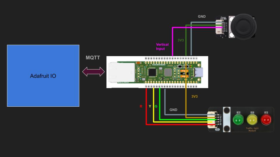
First, let's start with the Connection Diagram and the Online user interface of Adafruit IO.
The above is the structure of my project and the user interface.
The project is really simple. Locally on the board, you can turn on the lights from red to green by moving the joystick up, and by moving the joystick down, the lights will turn off from green to red. At the same time, you can press the up button from the controller to turn on lights from red to green or press the down the button to turn off lights from green to red.
The user interface will also what lights have been turned on or off below the power toggle button.
You can follow the written guide below or follow my Youtube video for the step-by-step guide.
Set up the boardBefore developing the project, we need to configure the block to become compatible with CircuitPython. Go to the download page of CircuitPython, search for W5100-EVB-Pico 2 and download the UF2 File onto your local computer.
Connect your board with the PC by holding the BOOTLEG button and connect to the PC.
Drag the UF2 file to the board's drive.
Your board should now consist of these files.
You can now connect the modules according to the connection diagram and also connect with the router with an Ethernet cable.
Set up user interfaceLet's start by making the user interface.
Go to Adafruit's Website and log in / sign up as a user.
After logging in, go to their IO page.
Find the feed page on top of the webpage and create 5 feeds which are
- Power
- Controller
- Red
- Green
- Blue
The first column is the name for the feed. The second column is the key to the feed. The third column is the most recent value pushed to the feed.
The key is used for data transfer between the evaluation board and the interface. The values inside these feeds affect the states of the user interface or the state of the evaluation board.
You can change the name or the key by clicking into the feed and press feed info.
Next, go to the dashboard tab.
Add a button block and bind it with the power feed.
Set On value as 1 and Off Value as 0.
This means that when the value inside the feed is updated to 1, this block will toggle onto On state. If the value is not equals to 1, this block will be on its off state.
Next, create a controller block and bind it with the control feed.
Press the buttons on the preview tab to check each value on the controller.
The only two button we will be using is the UP and DOWN button and their corresponding values are 5 and 13.
Lastly, make three indicator blocks for each of the color and bind the color feeds respectively.
Change title and On color to the color feed you have bind to. Set the condition to equals 1.0 so that only the value 1 will turn the indicator block on.
Configure the placement of the blocks as you want.
The set up for the interface is completed.
Preparation before codingBefore coding the project, we still need to download libraries to help us develop the project easier.
Go to the library page of CircuitPython, download the bundle zip folder containing MPY libraries onto your computer.
Extract these 5 files onto the lib folder of the board.
1. adafruit_io
2. adafruit_miniqtt
3. adafruit_wiznet5k
4. adafruit_connection_manager
5. adafruit_requests
Next, create a text file named as secrets.py onto the lib folder.
Go to this link and paste the JSON code onto the text file.
Find your name and token by going to Adafruit IO and press the KEY tab on top right of the page.
Paste the aio_name and aio_key to the secrets.py file. The other variables inside the JSON could be ignored as we will not be using them for this project.
Coding on CircuitPythonLets start coding our project using the web editor on CircuitPython.
Go to this CircuitPython's Code editor and remember to connect your board to the computer.
Press the connect tab, choose your device and open code.py on the code editor.
Required LibrariesStart by importing libraries to the file.
import time
import ssl
import board
from digitalio import DigitalInOut, Direction
from analogio import AnalogIn
import adafruit_connection_manager
import adafruit_requests
from adafruit_wiznet5k.adafruit_wiznet5k import WIZNET5K
from adafruit_io.adafruit_io import IO_HTTP, AdafruitIO_RequestError
import adafruit_minimqtt.adafruit_minimqtt as MQTT
from adafruit_io.adafruit_io import IO_MQTT
import adafruit_wiznet5k.adafruit_wiznet5k_socketpool as socket
Remember we also need the secrets.py file before using the Adafruit interface, so let's use the following code to check whether our lib folder consist of this file.
# Get Adafruit.io details from a secrets.py file
try:
    from secrets import secrets
except ImportError:
    print("You need secrets.py to run this program. Please add them to the lib folder.")
    raise
If there is no secrets.py file, the program will terminate immediately before the main code.Module and Board Ports Set Up
Next, let's set up the ports of the board with the modules.
According to the connection diagram, I have connected the Vertical component to GP26 for the Rocker Module and GP11, 13 and 15 for Green, Yellow and Red light respectively.
First, let's initialize the pin of GP26.
As our Rocker Module is an analog signal module, we use CircuitPython's AnalogIn funciton to set pin 26 as the analog input towards the board.
Dir_Vertical = AnalogIn(board.GP26) #UP/DOWNAs for the traffic light module, the module will receive digital signals from GP11, 13 and 15 to turn on their respective lights on the module. Therefore, we can use CircuitPython's DigitalInOut function to set the port as digital signals. We also need to change the direction to OUTPUT.
To turn on the light sequentially, we also need to create a list to store the 3 lights in the order of Red, Yellow and Green.
#Set LED as digital output
led_G, led_Y, led_R = DigitalInOut(board.GP11), DigitalInOut(board.GP13), DigitalInOut(board.GP15)
led_G.direction, led_Y.direction, led_R.direction = Direction.OUTPUT, Direction.OUTPUT, Direction.OUTPUT
led_set = [led_R, led_Y, led_G]
Side note: In W5100S-EVB-Pico 2, there are ports reserved for analog signals and for digital signals. You can refer to the following pictures or visit Wiznet's Official Website to find the ADC ports
Next, let's use the Ethernet function of the board.
Start by connecting the SPI interface Pin with CircuitPython.
For the specific pin of the board, you look at this graph provided from Wiznet's Ofifcial Website.
As you can see, pin 16-19 have specific use for the SPI interface for the board. Use the following code to set up the SPI interface.
# Initialize spi interface
import busio
cs = DigitalInOut(board.GP17)
spi_bus = busio.SPI(board.GP18, MOSI=board.GP19, MISO=board.GP16)
Combine them for Ethernet interface by using WIZNET5K function provided in adafruit.wiznet5k. Check the Github page for more information.
# Initialize ethernet interface with DHCP
eth = WIZNET5K(spi_bus, cs)
Next, to connect to the World Wide Web using HTTP, we need to set up a request session for the Ethernet interface. We can initialize a requests session with SSL by the codes below.
#Initialize a requests session
pool = adafruit_connection_manager.get_radio_socketpool(eth)
ssl_context = adafruit_connection_manager.get_radio_ssl_context(eth)
requests = adafruit_requests.Session(pool, ssl_context)
The requests session is reserved for HTTP requests. We can comment this line.
The finalized section for Ethernet Interface should as follow:
# Initialize spi interface
import busio
cs = DigitalInOut(board.GP17)
spi_bus = busio.SPI(board.GP18, MOSI=board.GP19, MISO=board.GP16)

# Initialize ethernet interface with DHCP
eth = WIZNET5K(spi_bus, cs)


#Initialize a requests session
pool = adafruit_connection_manager.get_radio_socketpool(eth)
ssl_context = adafruit_connection_manager.get_radio_ssl_context(eth)
requests = adafruit_requests.Session(pool, ssl_context)Let's start making our board a MQTT client ready to listen to Adafruit IO messages.
We can set up the client with this function.
# Setting Up MQTT client
mqtt_client = MQTT.MQTT(
    broker="io.adafruit.com",
    username=secrets["aio_username"],
    password=secrets["aio_key"],
    is_ssl=True,
    socket_pool=pool,
    ssl_context=ssl_context,
)
Inside the MQTT.MQTT function, there are several parameters we need to fill in before using the function.
Referring to the MQTT API Website of Adafruit, you can find the parameter of broker in the HOST Name in section MQTT Connection Details. As we stored our user authentication information in the secrets.py file, we can simply obtain these information from the secrets JSON and load into the MQTT function. Setting is_ssl to True allows us to connect to the Adafruit MQTT Api on 8883 Port. Lastly, we set the pool and context for our MQTT client by referring to the previous codes.
As we set up the client, we would need to create callback function for different purpose of the client.
In this project, we would like to make callback functions for when the client is connected, disconnect or receive / send messages.
# Set Callback function to different action of the MQTT client
mqtt_client.on_connect = connected
mqtt_client.on_disconnect = disconnected
mqtt_client.on_message = message
Connect Function
This function is called when we first connect to the Adafruit IO server. As we connect to the function, we should subscribe to the power feed and the controller feed.
Subscribing to a feed will allow any messages updated in that feed to trigger your message function. This is what your program will do whenever you receive a message from the feed you subscribed to.
In CircuitPython, you can use client.subscribe("some_topic") to subscribe to any topic/feed on the IOT platform.
However, different platforms may require different format of the topic. Therefore, we need to check the website's MQTT API page in order to look for the topic's format.
You can find the MQTT API Topic format in Adafruit's MQTT API page.
As shown above, the topic format is the form of
{username}/feeds/{feed key}
Therefore, let's make the power and controller feed into subscribable topics as we want any updates on both the power and controller feed to trigger the message function that affects our program.
Put these two topic in a list called subscribe_feed_list.
We need to also set the topic for the 3 LED lights as we also will be using this format to publish the data to these topics.
Put the 3 LED topics into a list of the order of Red, Yellow and Green as we want publish to these topics sequentially.
# initializing feed
power_feed = secrets["aio_username"] + "/feeds/power"
led_feed = [secrets["aio_username"] + "/feeds/red", secrets["aio_username"] + "/feeds/yellow", secrets["aio_username"] + "/feeds/green"]
controller_feed = secrets["aio_username"] + "/feeds/control"

subscribe_feed_list = [power_feed, controller_feed]
Lastly, inside the Connected function, we run a for-loop to subscribe to the two feeds.
# Define callback methods which are called when events occur
def connected(client, userdata, flags, rc):
    # This function will be called when the client is connected
    # successfully to the broker.
    for f in subscribe_feed_list:
        print("Connected to Adafruit IO! Listening for topic changes on %s" % f)
        # Subscribe to all changes on the feed list.
        client.subscribe(f)
Disconnect Function
This function will be called when we disconnect from the MQTT server.
In this project, I simply add a print statement to notify users that the client has successfully disconnected in the terminal.
def disconnected(client, userdata, rc):
    # This method is called when the client is disconnected
    print("Disconnected from Adafruit IO!")
Message Function
This function will be called when there is any updates in the subscribed topics.
As we subscribed to two different topics, we first need to identify which topic triggered the message function.
def message(client, topic, message):
    # This method is called when a topic the client is subscribed to
    # has a new message.
    print(f"New message on topic (topic}: {message}")

    if topic == power_feed:
        # change the power of the program

    elif topic == controller_feed:
        # Chang state of lights
Let's first define the function when we receive updates on the power topic.
The power button will toggle to on after we boot our device. As we previously designed our power toggle to turn on when the feed value is 1, we will publish a value of 1 to the power feed outside of these 3 function to notify the interface that we have turned on the device.
In the interface, the power toggle can be toggled to off by the user. This will cause the feed value to update to 0, where it should turn off the machine.
Therefore, we want to obtain the latest value on the power feed and determine whether our program stop or not.
# Inside topic == power_feed
# Turn device on/off based on latest value
global power
power = bool(int(message))
In this code, we use the global keyword to allow changes from this local function to the power variable located outside of this function. We then set the power to True or False depends on the latest value on the power toggle, which alters between 1 and 0.
Next, let's define the function when we receive updates on the controller topic.
When the user press any button on the controller block, a value will be posted in the controller feed. In our project, as we only use the UP and DOWN button, our function will only need to treat these two values, which is value 5 for UP and value 13 for DOWN.
elif topic == controller_feed:
    if int(message) == 5:         # Controller pressed Up
        # Turn On Algorithm

    elif int(message) == 13       # Controller pressed Down
        # Turn Off Algorithm
In the following section, I will be explaining the algorithms for turning on and off the lights respectively.
Algorithm for turning on the lights
Before turning on the lights, we need to deal with the maximum case first, that is if all the lights are turned on, we cannot continue to increase the number of lights to be turned on.
To trace the number of light turned on, I used a variable called current_light_on_pos to track the position of the current LED position that has been turned on.
That means Position 0 refers to only the Red light turned on, Position 1 refers to the Red and Yellow light are turned on, and Position 2 refers to all lights are turned on. An additional Position -1 is also included and initialized in current_light_on_pos, which refers to all lights are turned off.
Therefore, if the value of current_light_on_pos is 2, it refers to no more lights can be turned on, so we inform the user from the terminal that we cannot turn on anymore lights.
# Inside if int(message) == 5:
if current_light_on_pos == 2  :       # All lights are On
    print("Max_light_achieved")
After dealing with the maximum case, let's move on function for turning on the lights.
As we press the UP button on the controller, we should first increase the current_light_on_pos by 1 and turn on the light inside the list on the new position by using led_set[current_light_on_pos].value = True. Lastly, we publish the value 1 to Adafruit IO to the corresponding color topic as we want the interface to show which color have been turned on.
else:                                               # Not all lights are On
    # Light Response Algorithm (Turn On)
    current_light_on_pos = current_light_on_pos + 1 # Increase pointer
    led_set[current_light_on_pos].value = True      # Turn On the next light

    # Send Data to online interface
    mqtt_client.publish(led_feed[current_light_on_pos], 1)
Algorithm for turning off the lights
Similarly, let's deal with the minimum case first, that is when all lights are turned off.
If the value in current_light_on_pos is -1, it refers to all lights are turned off. Thus, we need to inform the user that we cannot turn off more lights in the terminal.
# Inside if int(message) == 13:

if current_light_on_pos == -1:            # if all lights are off
    print("Min_light_achieved")
After dealing with the minimum case, let's move on to the function for turning off the lights.
As we press the DOWN button on the controller, we should first turn off the light at current_light_on_pos inside the list by led_set[current_light_on_pos].value = False and publish the value 0 to Adafruit IO at the corresponding color feed. Lastly, we decrease current_light_on_pos by 1 to update the newest position of the current light that has been turned on.
else:
    led_set[current_light_on_pos].value = False   # Turn off the current light

    # Send Data to online interface
    mqtt_client.publish(led_feed[current_light_on_pos], 0)
    current_light_on_pos = current_light_on_pos - 1 # Decrease pointer
Lastly, as we will change the values of current_light_on_pos and the value inside led_set, we need to set them with global keyword inside the function.
This completes the message function of the MQTT Client.
Full message function:
def message(client, topic, message):
    # This method is called when a topic the client is subscribed to
    # has a new message.

    print(f"New message on topic {topic}: {message}")
    if topic == power_feed:

        global power
        # Turn this device On/Off based on the interface
        power = bool(int(message))

    elif topic == controller_feed:
        global current_light_on_pos, led_set

        if int(message) == 5:      # if online controller pressed UP
            if current_light_on_pos == 2  :   # All lights are On
                print("Max_light_achieved")
            else:
                current_light_on_pos = current_light_on_pos + 1 # Increase pointer
                led_set[current_light_on_pos].value = True  # Turn On the next light


                # Send Data to online interface
                mqtt_client.publish(led_feed[current_light_on_pos], 1)

        elif int(message) == 13:   #if online controller pressed DOWN
            if current_light_on_pos  == -1 :  # All lights are Off
                print("Min_light_achieved")

            else:
                led_set[current_light_on_pos].value = False   # Turn off the current light position

                # Send Data to online interface
                mqtt_client.publish(led_feed[current_light_on_pos], 0)
current_light_on_pos = current_light_on_pos - 1 # Decrease pointerLet's now complete the main program which the board will run.
We first start with initializing the remaining variable to be used in the program.
# Set power to True as we turned on the device
power = True
messages = {}Thepowervariable is used as the condition of the while-loop to keep running the main program until power becomes False ( which is turning off from the online interface). We should also initializemessagesvariable for using inclient.messagefunction.
Next, let's connect our defined MQTT client to the MQTT server, which is Adafruit IO.
Simply use the function MQTT.connect() function to connect to the server, which will simultaneously trigger our previously defined MQTT.connected() function. At the same time, we publish the value 1 to Adafruit IO to change the power toggle to On state.
# Connect the client to the MQTT broker.
print("Connecting to Adafruit IO...")
mqtt_client.connect()

# Notify the interface that the power has turned On
mqtt_client.publish(power_feed, 1)
Let's write the while-loop for the program. This while-loop will run until the power variable becomes False. Inside the while-loop, in order to maintain connection with the MQTT server, we need to use MQTT.loop().
while power:
    mqtt_client.loop()
    # ... Do Rocker Module with Light Response Function ...
For the function inside the while-loop. we want the inputs of the rocker module to turn on or off the lights. Let's define the value read_Vertical = Dir_Vertical.value for storing the current value of the joystick vertical value. Then, we simply use the same light response algorithm we previously defined, but with different condition to trigger both the light on function and light off function.
You can set your own threshold for your code, but I have use 60000 as the upper threshold for turning on the lights and 3000 as the lower threshold for turning off the light.
Lastly, add a time.sleep function to limit the instructions of the while-loop.
while power:
    mqtt_client.loop()
    read_Vertical = Dir_Vertical.value

    # Light response function
    if read_Vertical >= 60000:  # Increase number of light turned on if Joystick goes up
        if current_light_on_pos == 2  : # All lights are on
            print("Max_light_achieved")
        else:
            current_light_on_pos = current_light_on_pos + 1
            led_set[current_light_on_pos].value = True
            # Send Data
            mqtt_client.publish(led_feed[current_light_on_pos], 1)

    elif read_Vertical <= 3000: # Decrease number of light turned on if Joystick goes down
        if current_light_on_pos  == -1 : # All lights are Off
            print("Min_light_achieved")
        else:
            led_set[current_light_on_pos].value = False
            # Send data
            mqtt_client.publish(led_feed[current_light_on_pos], 0)
            current_light_on_pos = current_light_on_pos - 1

time.sleep(0.5)Lastly, when we quit the while-loop, we need to reset everything on the interface to its default state and disconnect from the server. Simply run a for-loop and publish the corresponding default values to the power feed and the LED feeds, which are all 0s and disconnect from the server afterwards.
# Power turns Off
print("Power is off")

# Reset to Default Values on Adafruit IO
for y in range(current_light_on_pos + 1):
    mqtt_client.publish(led_feed[y], 0)
mqtt_client.publish(controller_feed, 0)

#Disconnecting From the Server
mqtt_client.disconnect()

print("Machine Tunred off")This concludes the project codes and setup. You can code according to the above steps or try out the codes in the GitHub page. If you have any questions, you could also comment onto the YouTube video. I hope this helps you understand more on how to use the W5100S-EVB-Pico 2 on CircuitPython and kick start your first IoT creation journey.


Comments
Please log in or sign up to comment.