


Hardware components | ||||||
_ztBMuBhMHo.jpg?auto=compress%2Cformat&w=48&h=48&fit=fill&bg=ffffff) |
| × | 1 | |||
 |
| × | 1 | |||
 |
| × | 5 | |||
 |
| × | 1 | |||
 |
| × | 1 | |||
 |
| × | 1 | |||
 |
| × | 1 | |||
 |
| × | 1 | |||
Software apps and online services | ||||||
 |
| |||||
We haven't found a place to put the video demo T_T
It will be 10 times more interesting if you see the demo video.
here are some pictures:
This project is a simple school project done by four high school students
the main purpose for this project is for inspiration new idea and problems solving.
you can consider it as my own note, or a basic tutorial for those who are new to Arduino like me.
it's not a high-tech project and it has defect in many aspects, but you can always learn something if you try to start.
you don't need to follow the exactly the same step, try different approach, search and ask question on the internet has always been a good way to make progress.
I want to thanks to my wonderful teammates 安妮老师(Annie), Michael, and Frank for your wonderful support!
and if this article involving infringement, please comment below or email me: 3033776780@qq.com
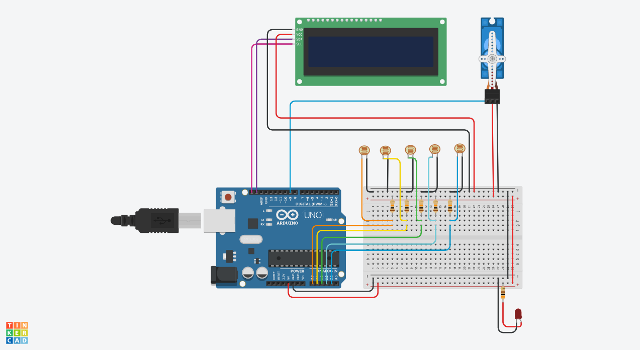
Get started:Set you Arduino with the bread board like below
- 5V Pins: stand for the power
- GND: stand for the ground.
- LED: just note that anode is longer, it's basically a light source
now the bread board has two lines one makes in '+' connect to the power supply and one in '-' connected to the ground.
this arrangement provides you with much more space when you have multi equipment requiring
a 5V connect to it.
(Reminder: the dots on the bread broad are connected together in column on the middle and in row on the two side.)
LED street-light:Now you can light a LED, as the streetlight, remember you have to connect it with a proper resistor(300ohm), otherwise it may face the risk of overheat.
LDR (Light-dependent-resistor)- LDR's resistor vary with the light intensity.
- A0 to A5: used to read analogue data in this project
higher the intensity, lower the resistor.
It's used to detect weather there is object above it.
connect the LDR and the 10kohm resistor in series, as the LDR's resistor varies, the resistor divides the voltage, and the value is read by A0.
A0 here is playing the role of an analogue to digital convertor (ADC).
once you have successfully connected, you can connect the series of LED and resistor with its anode to one of the GPIO pins on top of Arduino uno
//check whether the LDR is working properly
const int LIGHT_SENSOR_PIN = A0; // pin for read
const int LED_PIN = 5; // pin for output
const int ANALOG_THRESHOLD = 300; // a standard value for ldr, change this if not working
int analogueValue;
void setup(){
   pinMode(LED_PIN,OUTPUT); //set the pin mode for output power
}
void loop() { // this loop repeate itself over and over again
   analogueValue = analogRead(LIGHT_SENSOR_PIN); // update the value from the LDR
   if(analogueValue < ANALOG_THRESHOLD){ //if it's getting too bright
       digitalWrite(LED_PIN, LOW);
   }
}
once you have done this, duplicate 4 more LDR
A0 for the gate and rest for the parking place.
Servo motor- Servo motor: this kind of motor have an inbuild encoder which read PWM wave
- PWM: Pulse Width Modulation, think it as a wave sending a sequence of 1 and 0, the percentage of time the signal 1 occupy is called duty time, which decide the performance of a motor or a light.
we choice '~9' for sending PWM wave and the remain two pin for power supply
 //cheak whether the servor motor is working properly
#include <Servo.h> // library for controling the servo motor
Servo myservo; // declear a variablewith the type servo
void setup(){
 myservo.attach(9); // attach the servo to our servo object
 myservo.write(90); // 90 stand for stay still, it convert the duty time more read able
}
void loop(){
 myservo.write(45); // rotate clockwise
 delay(5000); //obtain the current situation for 5 sec
 myservo.write(90);
 delay(3000);
 myservo.write(135); // rotate anti-clockwise
 delay(5000);
}
!!! note that I use 360-degree servo motor instead of 180-degree one, find the code for 180-degree yourself as a good practice. it may perform better :D
16x2 LCD scream with I2C- 16x2 LCD scream: a 2 rows times 16 columns LCD scream
- I2C: Inter-Intergrated Circuit, bidirectional bus which easily implemented any IC process, to communicate with consumer product, it can reduce the occupation of GPIO on Arduino broad, and much easier with coding.
- SCL: Serial clock line
- SDA: serial data line
The hardware device I use is welding a normal 16x2 with a I2C hard drive, therefore I need to change the backlight setting physically with a screwdriver.
// check whether the 16x2 I2C LCD scream is working properly or not
#include <Wire.h>
#include <LiquidCrystal_I2C.h> // https://github.com/fdebrabander/Arduino-LiquidCrystal-I2C-library
LiquidCrystal_I2C lcd(0x27, 16, 2);
void setup(){
 lcd.begin();
 lcd.backlight(); // set the backlight for display
 lcd.setCursor(0, 0); // the position of the curosr on the scream
 lcd.print("Hello world!"); // the out put
}
void loop(){
 // leave this empty
}
!!!
things to notice:
- the library for I2C 16x2 is not provide by the Arduino IDE, I find it on Github: https://github.com/fdebrabander/Arduino-LiquidCrystal-I2C-library
- clone it to the library document in Arduino ide
- then you should be able to import it.
if you scream is not able to display anything:
- check the setting of backlight
- check the physical location of you scream
use the scanner code and see the output on the Arduino serial monitor change the variable 0x27 with the one you get.
// for display 16x2 local adress
#include <Wire.h>
void setup()
{
Wire.begin();
Serial.begin(9600);
Serial.println("\nI2C Scanner");
}
void loop()
{
byte error, address;
int Devices;
Serial.println("Scanning...");
Devices = 0;
for(address = 1; address < 127; address++ )
{
Wire.beginTransmission(address);
error = Wire.endTransmission();
if (error == 0)
{
Serial.print("I2C device found at address 0x");
if (address<16)
Serial.print("0");
Serial.print(address,HEX);
Serial.println("  !");
Devices++;
}
else if (error==4)
{
Serial.print("Unknown error at address 0x");
if (address<16)
Serial.print("0");
Serial.println(address,HEX);
}
}
if (Devices == 0)
Serial.println("No I2C devices found\n");
else
Serial.println("done\n");
delay(5000);
}
now, you have all the hardware ready, test and try the finial code below, change some variable and improve it with your own ideas.
make the setup nice and decent and place some model car :D
last but not least, have fun!!


Comments
Please log in or sign up to comment.