RC cars are always fun to play with, I am personally a big fan of these remote-controlled Cars and have played (still do) with them extensively. Most of these cars today provide a huge torque to handle rough terrains, but there is something that was always lagging, its Speed!!.. So, in this project, we will build a totally different type of RC car using Arduino, the main objective of this car is to achieve maximum speed, hence I decided to try out the coreless DC motor for an RC car. These motors are normally used in drones and are rated for 39000 RPM which should be more than enough to quench our speed thirst. The car will be powered with a small lithium battery and can be controlled remotely using the nRF24L01 RF module. Alternatively, if you are looking for something simple, you can also check this Simple RF Robot and Raspberry Pi Bluetooth Car projects.
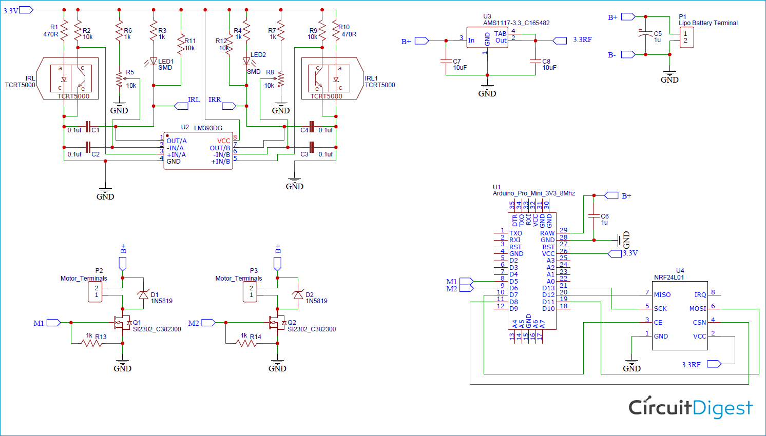
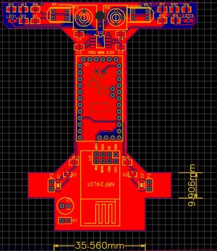
Fabricating PCB for Arduino RC CarThe fun part with the building this project was the PCB Development. The PCB’s here not only forms the circuit but also acts as a Chassis for our Car, so we planned a car looking shape for it with options to easily mount our motors. You can also try designing your own PCB using the circuit above or you can use my PCB design which looks like this below once completed.
As you can see I have designed the PCB to easily mount the battery, motor, and other components. You can download the Gerber file for this PCB from the link. Once you are ready with the Gerber file, its time to get it fabricated. To get your PCBs easily done by PCBGOGO follow the steps below
Step 1: Get into www.pcbgogo.com, sign up if this is your first time. Then, in the PCB Prototype tab enter the dimensions of your PCB, the number of layers and the number of PCB you require. My PCB is 80cm×80cm so the tab looks like this below.
Step 2: Proceed by clicking on the Quote Now button. You will be taken to a page where to set a few additional parameters if required like the material used track spacing etc. But mostly the default values will work fine. The only thing that we have to consider here is the price and time. As you can see the Build Time is only 2-3 days and it just costs only $5 for our PSB. You can then select a preferred shipping method based on your requirements.
Step 3: The final step is to upload the Gerber file and proceed with the payment. To make sure the process is smooth PCBGOGO verifies if your Gerber file is valid before proceeding with the payment. This way you can sure that your PCB is fabrication friendly and will reach you as committed.


 PCBGOGO Mike


Comments
Please log in or sign up to comment.