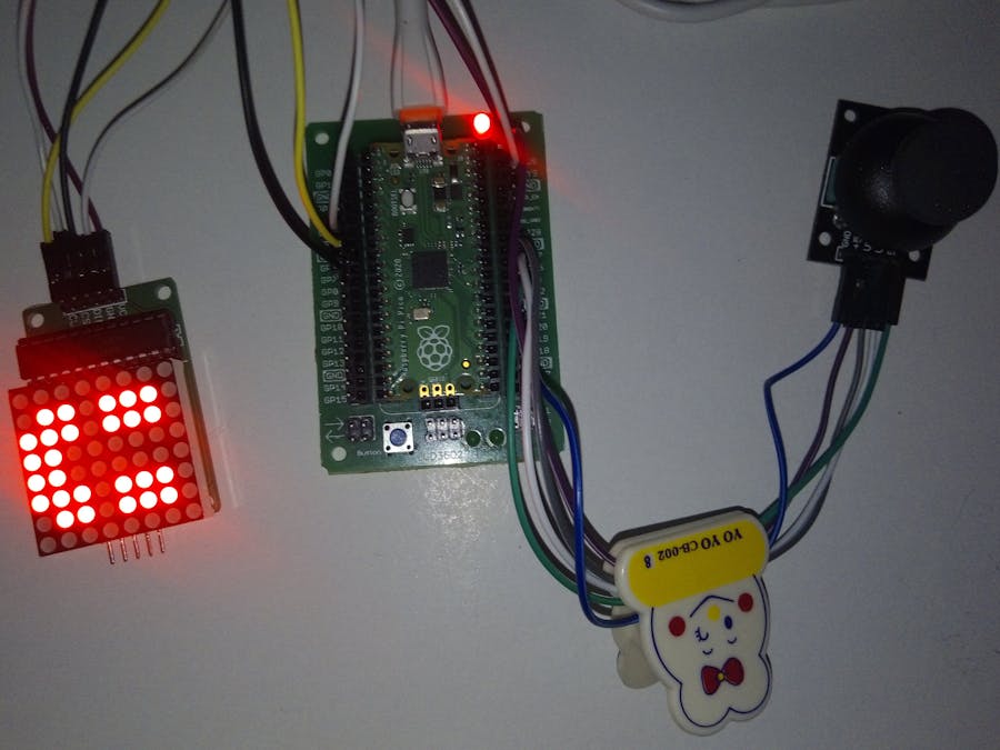
Welcome to this project where I will be creating an exciting games using MicroPython and Raspberry Pi Pico.
In this project, I will connect a joystick controller and an 8x8 LED matrix to the Raspberry Pi Pico to build our games.
The idea for this project came from our love of retro games and our desire to create something fun and interactive using micro python. We wanted to create a game that was simple but challenging, and that could be played by people of all ages.
I chose to use the Raspberry Pi Pico because of its affordability and ease of use. The Pico is a powerful microcontroller that can be programmed using micro python, which is a beginner-friendly language. I also chose to use a joystick and LED matrix because they are simple components that can be easily connected to the Raspberry Pi Pico.
My goal with this project is to inspire others to create their own retro-style games using micro python. I believe that programming can be fun and accessible to everyone, and I hope that this project will encourage more people to explore the world of microcontrollers and game development.
Description:In this project, we will leverage the power of MicroPython programming language to develop a Ping Pong game and snake game. The Raspberry Pi Pico, a microcontroller board, will serve as the brain of our project. We will connect a joystick controller to the Raspberry Pi Pico, allowing players to control the movement of the paddle in the game or snake movment.
Additionally, we will integrate an 8x8 LED matrix into our setup. This LED matrix will display the game graphics and provide visual feedback during gameplay. By combining these components, we can create an interactive and engaging games experience.
Our journey begins with exploring the capabilities of Raspberry Pi Pico and understanding how to program it using MicroPython. We will set up the necessary development environment and install required libraries for controlling the joystick and LED matrix.
If you want to make a PCB for this project or 3D print enclosure, or for any other electronic project, PCBWay is a great choice for you. PCBWay is one of the most experienced PCB manufacturing company in China in field of PCB prototype and fabrication. They provide completed PCB assembly service with worldwide free shipping, and ISO9001 quality control system. Also, on their site there is an online Gift-shop for ordering the tools.
PCBWay has a dedicated component store in addition to PCB services. PCBWay GIFT SHOP is an online marketplace from which we can source all the major electronics stuff, like Raspberry Pi boards, Displays, wires, etc.
https://www.pcbway.com/project/gifts_list
PCBWay has this system that lets us purchase anything from their gift shop with beans. Beans are like redeemable currency or coupons that we get by placing an order on PCBWay or by sharing your projects in the community to get beans.
Raspberry Pi Pico:
The Raspberry Pi Pico is a microcontroller board based on the Raspberry Pi RP2040 microcontroller chip. It has been designed to be a low-cost, high-performance microcontroller board with flexible digital interfaces. The Raspberry Pi Pico features two ARM Cortex-M0+ cores run up to 133MHz; 256KB RAM; 30 GPIO pins; and a broad range of interfacing options. This is paired with 2MB of onboard QSPI Flash memory for code and data storage.
In addition to powerful hardware resources, Pico has rich and complete software support and community resources. It comes with a complete Rasberry Pi official C/C++ SDK, Micropython SDK. Just click https://pico.raspberrypi.org/getting-started/ to get started with Raspberry Pi Pico.
Features:
Breakout Module Shield PS2 Joystick Game Controller:
- Breakout module for analog joystick.
- 5 pins on board: VCC, GND, X, Y and Button. Connect the module with 5V power suppy with VCC and GND, you can read out the joystick status by X, Y and button pins.
- When using the 5V power supply, the default analog output for X, Y is 2.5V. With the direction of the arrow, the voltage up to 5V, and the opposite direction down to 0V.
- Package Dimension : 7.62 centimeters L x 5.588 centimeters W x 1.777 centimeters H.
Wiring a Joystick to Raspberry Pi Pico
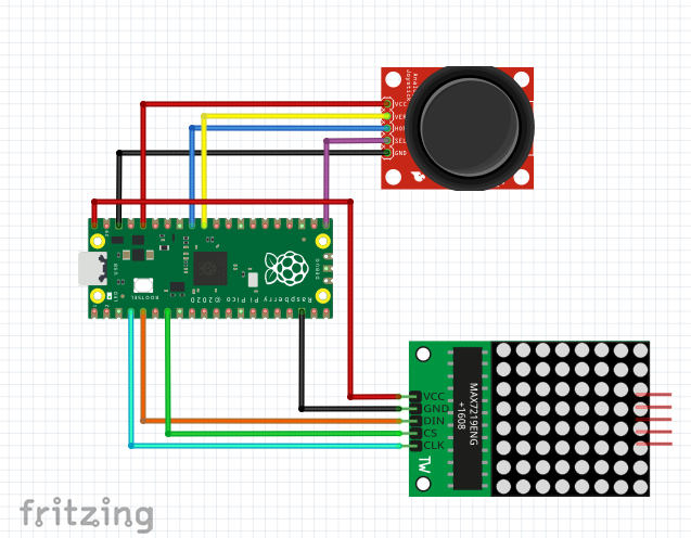
Wire the joystick’s 5 pinsto the Pico as follows:
- GND to GND (Any GND pin)
- +5V to 3V3 Out (physical pin 36). Yes, a 5V joystick will work with the 3V3 power of Pico.
- VRx to GP27 / ADC1 (physical pin 32)
- VRy to GP26 / ADC0 (physical pin 31)
- SW to GP16 (physical pin 21). This would work with most of the GPIo pins.
An analog thumbstick is effectively three devices in one: a potentiometer for the X axis, a potentiometer for the Y axis and a digital momentary button when you press down.
The internal circuit diagram of the joystick module is shown below:
Read More: https://www.tomshardware.com/how-to/raspberry-pi-pico-joystick
MAX7219 LED Dot Matrix Display with Raspberry Pi Pico:
MAX7219 LED Dot matrix display is one of the popular ones available in the market and used by students, electronics hobbyists, and especially in industrial display applications. There are two types of modules generally available. These are the FC-16 module and the generic module.
Each module consists of two units. One is the 8X8 LED dot matrix and the other is the MAX7219 IC.
MAX7219 has a built-in BCD decoder that makes it easy to use with seven segment numeric displays. Additionally, it has an 8×8 static RAM that we can use to store numbers. It is one of the most popular displays driver IC.
Some key features of MAX7219 include:
- It is an LED driver display IC with a 10MHz serial interface which allows the user to select the decode/No-Decode digit.
- Its operation is specified in a voltage range of +4.0 to +5.5V. Normally, the voltage supply of +5V is used.
- It provides a feature of digital and analog brightness intensity control and a 150µA shutdown mode in which the current of all segments is pulled to ground.
- It consumes very low power.
- The data is displayed on segments with a delay time of 2.2ms.
- MAX7219 works well in a temperature range of 0°C to +70°C.
- The maximum current for each segment pin is 100mA and for each DIGIT ground pin is 500mA.
The input connections of the LED matrix are connected with Raspberry Pi Pico
- VCC: This pin supplies power to the MAX7219 module. It is connected with 5V pin of Raspberry Pi Pico.
- GND: This is the ground pin which should be connected with the ground pin of Raspberry Pi Pico.
- DIN: This is the data in pin. It is used as the SPI input to the module.
- CS: This is the Chip Select pin for SPI communication.
- CLK: This is called the ‘Serial Clock’ pin which is used in SPI serial clock output.
Read More: https://microcontrollerslab.com/max7219-led-dot-matrix-display-raspberry-pi-pico/
Snake Game with Raspberry Pi Pico 🐍😀🕹️The snake algorithm flow diagram is shown below:
The algorithm I wrote is similar to the previous diagram.
When the game is over, we have stored arrays to display appropriate emojis that you can change 🙂😐😢
When you press the digital momentary button at any moment, it displays the result we have achieved 🧮🙂🕹️🐍️⁉️
Learn more: https://onlinedocs.microchip.com/pr/GUID-57DEB6DD-1115-4A93-9515-41ACCB7164AE-en-US-4/index.html
PingPog Game with Raspberry Pi Pico 🕹️😀🏓Now, I will dive into designing the game logic. I'll define rules for scoring points, detecting collisions between the ball and paddle, and handling player input from the joystick controller. Through careful coding and testing, we aim to create smooth game-play with responsive controls.
Below are the steps used:
Step 1) Create two paddles A and B on the left and right side of the screen 🏓
Step 2) Create a ball 🥎
Step 3) Create an event to move the paddle vertically depending on joystick movement 🕹️
Step 4) Create the function to update the score after each player misses a collision 🧮
When you press the digital momentary button at any moment, it displays the player1_score or player2_score that has achieved more points ('A' or '=' or 'B') 🙂⁉️
Learn more:
https://www.geeksforgeeks.org/create-pong-game-using-python-turtle/
https://almettkidscoding.github.io/basics/pong_game/


_1x_bGT19vVAby.png?auto=compress%2Cformat&w=40&h=40&fit=fillmax&bg=fff&dpr=2)


Comments