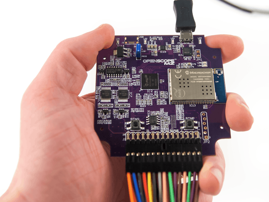
In this tutorial, we will go over how to connect an OpenScope MZ to LabVIEW. To do so, I will be walking you through some example VIs that I made. These examples allow you to access the oscilloscope and Wavegen/DC power supply functions of the OpenScope as well as the GPIO pins and the Logical Analyzer.
Hardware
Software
NOTE: Installing LabVIEW requires you create an NI account. Your LabVIEW installation and any NI software keys you use will be tied to this account.
Hardware setupA full OpenScope MZ setup guide can be found here. I will go through a brief overview of the steps found on that page.
Download and install the Digilent Agent.
1) Connect the OpenScope MZ to the computer via USB.
2) Right click the Digilent Agent in the system tray and click Launch WaveForms Live.
3) Add the Digilent Agent and OpenScope MZ to WaveForms Live.
- Click Add A Device.
- Choose Agent.
- Enter the hostname or IP address of the device where the Agent is running and click Add Device.
- Select the COM port associated with the OpenScope MZ from the drop down.
- Click Update Firmware and follow the instructions to update the firmware on the OpenScope MZ.
- Next, Under the Calibration section click Calibrate and follow the steps to calibrate your device.
Finally, connect your device to WiFi by following the steps on this page. Once you have your OpenScope connected to WiFi you are ready to move on to the next steps.
OpenScope MZ Communication ProtocolThis page is a reference for the OpenScopes communication protocols. All open scope commands are JSON objects (start with '{' and with '}' or OSJB (in chunk notation). Add JSON command that went sent via terminal puts the device into JSON command mode. Below is an example command that you would use to reset the device.
The Send box on the left contains the code that you will be sending to the device while the Response box contains the expected response. To send this command from LabVIEW, you will use the HTTP POST VI that can be found in the HTTP Client Palette. You can see an example of this VI in the picture below.
This LabVIEW VI has you input the OpenScopes URL (http:// followed by it's IP address) and the JSON command that you want to say. It then outputs a response. The picture below shows the response I received after sending the Reset Instrument command that I show above.
Now that you have a basic understanding of how to communicate with the OpenScope from LabVIEW I will walk you through each of my three example VI's.
GPIOThis LabVIEW example allows you to access the GPIO data and functions. You can set the parameters(direction) of the specified GPIO channels as well as read the specified GPIO channel(s) or Write the output voltage(s) of the specified GPIO channel(s). The VI Front Panel is shown below.
This example allows you to switch the I/O channels between input and output by using the Boolean controls at the bottom. When a channel is set to input, it will turn red if it's input is high. In the block diagram below you can see the HTTP POST VIs that I used to accomplish this, along with an explanation for each part.
This LabVIEW example allows you to access the logic analyzer instrument data and functions.
This example allows you to adjust the trigger parameters by changing the "triggerSetParameters Send" control. You can do this by changing the numbers next to "risingEdge": and "fallingEdge": to the decimal equivalent of the 10-bit binary number where each bit represents a corresponding channel. So to clarify:
- # of channels rising edge =
- 0 channels = 0000000000 = 0
- Channel 1 = 0000000001 = 1
- Channel 2 = 0000000010 = 2
- Channel 3 = 0000000100 = 4
- Channel 4 = 0000001000 = 8
- Channel 5 = 0000010000 = 16
- Channel 6 = 0000100000 = 32
- Channel 7 = 0001000000 = 64
- Channel 8 = 0010000000 = 128
- Channel 9 = 0100000000 = 256
- Channel 10 = 1000000000 = 512
The number that you pick will be the sum of the of the channels decimal values. So If you wanted to set it to trigger when Channel 1, 3 and 5 were rising and when Channel 2, 4 and 7 were falling you would set it up as follows
"risingEdge": 21     (1 + 4 + 16)
"fallingEdge": 74     (2 + 8 + 64)
In the block diagram below you can see the HTTP POST VIs that I used to accomplish this, along with an explanation for each part.
This LabVIEW example shows you how to access the oscilloscope instrument data and functions. It also allows you to access the data and functions for the DC power supply and the Arbitrary Waveform Generator.
In this example you are able to set the parameters of the waveform by changing the Waveform send command, The parameters you can change are shown below:
          "signalType":"square",
          "signalFreq":1000000,
          "vpp":3000,
          "vOffset":0,
          "dutyCycle": 50
You are also able to change the DC Voltage supplied and the trigger parameter for the Oscilloscope. In the block diagram below you can see the HTTP POST VIs that I used to accomplish this, along with an explanation for each part.
Thank you for reading my tutorial, if you are interested in trying out these examples yourself but don't have the right supplies you can purchase LabVIEW 2014 home bundle for only 50 dollars. You can also purchase the OpenScope MZ on Digilent's website. Please comment with any questions or comments you may have.


Comments
Please log in or sign up to comment.