

Hardware components | ||||||
| × | 1 | ||||
| × | 4 | ||||
| × | 1 | ||||
Software apps and online services | ||||||
 |
| |||||
Or stay upright to get there!
IntroductionIn an earlier article, the test exercise consisted of reading basic compass heading with suggestions on calibration. As the note mentioned, these readings are susceptible to any non-planar movement of the assembly. This article introduces a basic improvement in the estimations by integrating an accelerometer to the revised solution.
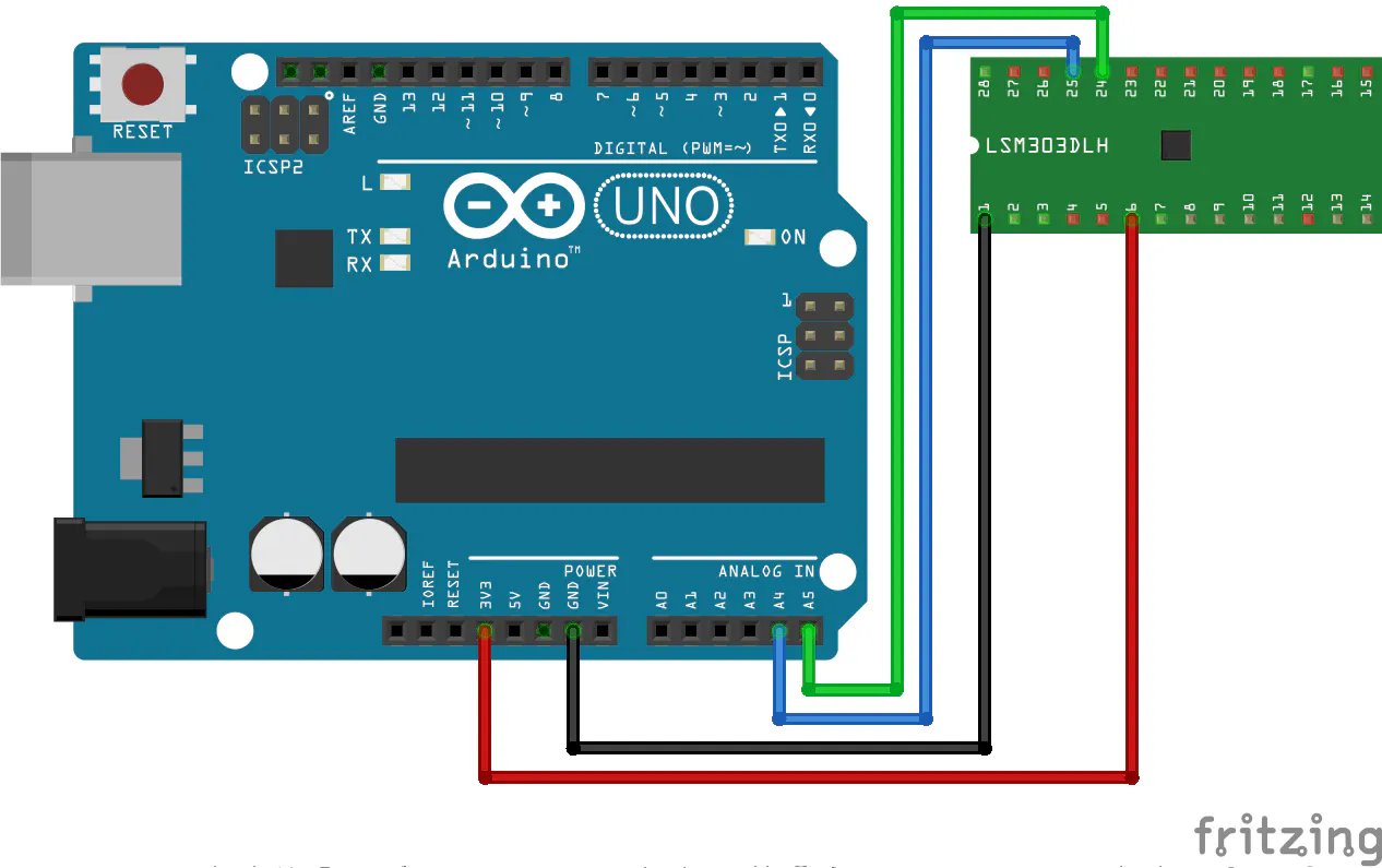
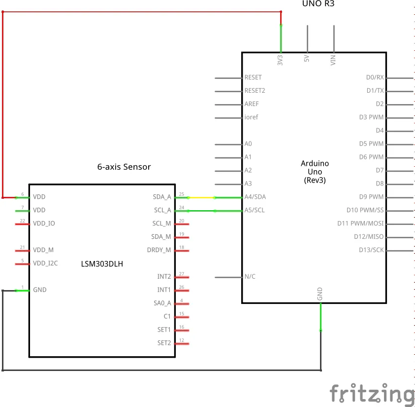
The example for the limited purposes of an introductory exercise uses the Grove 6-axis (3D for compass and 3D for accelerometer) sensor for the exercise with an Elegoo Arduino UNO board and a breadboard assembly. The core integrated module, LSM303DLH, for the sensor generates interrupt signals upon customer settings for detection of changes in motion and magnetic field. While the module provides SPI and I2C interfaces, the Grove sensor supports the I2C interface only with the required pull-up resistors, capacitors and supporting circuitry on a small printed circuit board (PCB) where the integrated module is surface mounted. In other words, the sensor supports connection to the SDA/SCL pins on the UNO relying on the I2C interface only.
ApplicationsThe integration of the accelerometer extends the application of compass readings to situations where movement occurs such as:
- Pedometers
- Fall detection
- Click detection
- Activity for power management of portable/mobile devices
- Tilt corrected compass
The key features of the LSM303D family of modules are:
- Compass, 3-axis data
- Accelerometer, 3-axis data
- Scaled output for compass and accelerometer data
- 16-bit data precision for output
- I2C and SPI interfaces
- Autonomous power-down modes for accelerometer and compass
The following table summarizes the pin connections for the Grove assembly of the sensor module. The latter’s rich set of pins are inaccessible for the limited purpose of this exercise since it is surface mounted on a Grove format small printed circuit board with the supplementary circuitry including pull-up resistors and voltage levelers.
Pin Description Color UNO
1 GND Black GND
2 VCC Red +3.3V
3 SDA White 18
4 SCL Yellow 19
Electrical specificationsI2C interfaceTheI2C interface provides access to the module as follows:
- SCL for the serial clock to:
- Initiate data transfer
- Generate clock signals
- Terminate data transfer
- SDA for the serial data to:
- Send or receive data
The calibration of the module occurs at the factory. The module retains the correction factors in non-volatile memory. During initialization of the module, specific registers receive these correction factors. The assembled board does not require further calibration for simple routine test exercises.
I2C addressesTheI2C scanner application, LMS303D-01.ino, detected the addresses for the accelerometer and the compass respectively as shown below:
Scanning...
I2C device found at address 0x18, 0d24, 0o30, 0b11000
I2C device found at address 0x1E, 0d30, 0o36, 0b11110
done
Each line identifies a single address expressed in hexadecimal, decimal, octal and binary representations.
AccelerometerThe core test file, LMS303D-04.ino, had extraneous print statements removed to display only raw X, Y, Z axes values which were rendered in the serial plotter window as shown below:
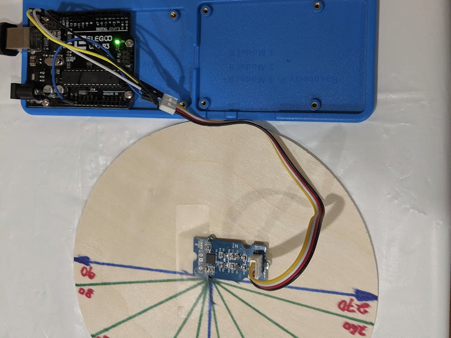
As the legend indicates, the X, Y and Z values are in blue, red and green colors. The LMS303D was mounted on a planar disk as shown in the photo below.
The disk was rotated manually (i.e. imprecisely, unscientifically) along the three coordinate axes individually. The parametric changes can be seen in the plotter window. Ignoring the imperfections of hand movements, the movement for each axis can be easily visualized(although there is some interference from the other axes owing to the erratic hand movement).
In the final phase, an arbitrary rotation in all three axes was applied and the corresponding output shows all values changing concurrently.
CompassThe sketch was further modified, LMS303D-04.ino, to graphically illustrate the compass movement. Two values are displayed in the plot below – raw and tilt compensated. For the purpose of this exercise, the rotation was limited to the Z axis.
The disk was rotated in the Z axis (yaw) for these readings as illustrated below:
Once it is established that the corrected readings are within the expected range then only the computed heading is sufficient for use within an application. The other data values may serve some purpose in debugging or related (but separate) visualization displays but these values are already applied to correct the raw compass reading and are therefore redundant for the limited purposes of this introductory note. Other geomagnetic adjustments may still be necessary (e.g. terrestrial magnetic influence based on geographic location) if the sensor is transported over longer distances. These topics are not discussed here but anyone wishing to deploy practical projects with this sensor may wish to review published datasheets for further exploration.
If compass readings are required in an environment where movement of the sensor occurs in three dimensions then the compass reading must be adjusted with accelerometer data to offer a nominally better reading. The sensor used in this exercise supports this approach while providing access to the underlying raw data for the compass (3 axes) and accelerometer (3 axes).
The Next StepsThis article is the second of a series on estimating headings (and eventually location):
- Compass only (3-axis) – published previously
- Compass and accelerometer (6-axis) – current article
- Compass, accelerometer and gyroscope (9-axis) – future article
- Compass, accelerometer, gyroscope and GPS – (TBD)
Computing tilt measurement and tilt-compensated e-compass


Comments