In this tutorial, we’ll see how to convert digital data in analog and re-convert this data in digital to check the signal, in particular, we use a cosine function.
We’ll use Zerynth Studio to program the microcontroller-based board in Python.
Zerynth simplifies and speeds up IoT development allowing programming in Python or hybrid C/Python the most popular 32-bit microcontrollers and connecting them to the leading Cloud Infrastructures like AWS, Google Cloud, Microsoft Azure, IBM Watson, Ubidots, and many more.
Before development, let's analyze the libraries we're going to use.
In the standard library, we find the “Math” module for all the trigonometric functions, such as tag(x), cos(x), sin(x), the function degree() and radiant() for converting an angle in radians to degree and vice versa.
Before introducing the two libraries that manage the signals we see a brief explanation of the difference between analog and digital signals.
An analog signal varies continuously over time, i.e. it can take on infinite different values. A digital signal, on the contrary, can assume a finite number of different values.
This module loads the Digital Analog Converter (DAC) interface. A digital to analog converter is a module to convert digital values into analog ones. It is used to write the cosine signal (a pure digital signal) in analog waves.
This module loads the Analog to Digital Converter (ADC) driver of the embedded device. It is used to read the data of signals and then make the plot with “oscilloscope”.
This module defines classes used in high-level threaded programming. Zerynth VM offers native low-level primitives for multithreaded programming that can be difficult to use. It is used to read the input of analog signals in a different thread.
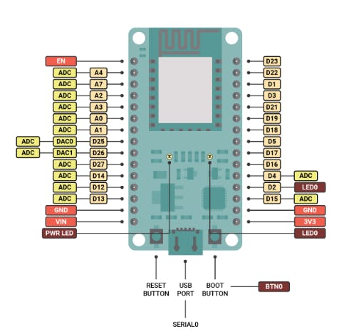
Required Material- First of all, you need a board. You can select one of the 32-bit microcontroller devices supported by Zerynth. We’ve chosen the ESP32-DevkitC by Espressif (read Zerynth documentation here).
- Zerynth Studio, a powerful IDE for embedded programming in Python that enables the IoT. You can download it here.
- Breadboard and/or wire for connecting two pins.
Pay attention to the pins.
You can write analog signals in A2, A3, A4, D33.ADC, D34.ADC pins, while D25 and D26 pins are marked as DAC even if in the board serigraphy are called A0 and A1.
You have to connect with a cable the D25 pin with A4.
Programming1. Zerynth Setup, Connect and virtualize the device. If this is your first time using Zerynth studio, Follow this documentation on getting started with Zerynth Studio IDE.
2. To give you a brief example of C/Python programming, open the examples bar, open the “DAC Basic” then clone it.
3. Once cloned the example you can test the basic functioning of the library (remember to set the pin correctly). At this point, you can add the Math module and try to print the cosines of an array of angles.
4. Finally, by adding the print of the trigonometric functions that you find in the basic example of the Math module you can see the signal graphed. (The result must be like the code below).
This example can be a starting point for a project where you are going to compare an external signal with a trigonometric function (using multiple threads to manage the two signals).


_xIl5PcEdnz.png?auto=compress%2Cformat&w=40&h=40&fit=fillmax&bg=fff&dpr=2)
Comments
Please log in or sign up to comment.