


Software apps and online services | ||||||
 |
| |||||
 |
| |||||
Hand tools and fabrication machines | ||||||
 |
| |||||
 |
| |||||
This project is an extension of the Lily∞Bot motion control project. It will show how to add infrared sensors, write code to test infrared sensors and use infrared sensors for potential field or proportional control obstacle avoidance on the robot.
I am an open-source hardware trailblazer and this is part of my guidebook to show academics how to engage in open source hardware for education, service, and research by using open-source robots.
- Professional website: https://wordpress.rose-hulman.edu/berry123/open-source-hardware-trailblazer/
- Business website: https://noiresteminist.com/
- YouTube playlist on channel: https://youtube.com/playlist?list=PL175eO9NwPXJm3xZPF113ve4L6tO8ckNi
- Instructables: https://www.instructables.com/member/carlottaberry/settings/?cb=1658526069
- Hackster.io: https://www.hackster.io/berry123
Arduino Uno Robot Infrared Sensor
Build the LilyBot by following the project at this link.
Step 2 - Acquire SuppliesIf you have already built the LilyBot, these are the additional supplies that you wil need.
- 4 Sharp IR Sensors (GP2Y0A02YK or GP2Y0A21YK0F)
- 4 IR cables
- 8-8 mm Phillips head panhead stainless steel machine screws
- 4 IR sensor mounts 3d printed from GITHUB files here
- one LED
- obe 220Ω resistor
- mini Phillips head screwdriver
- Use the 8-8 mm screws to attach the 4 Sharp Infrared sensors to the IR mounts.
- Screw the mounts into the top chassis of the Lily∞Bot in the front, back, left and right.
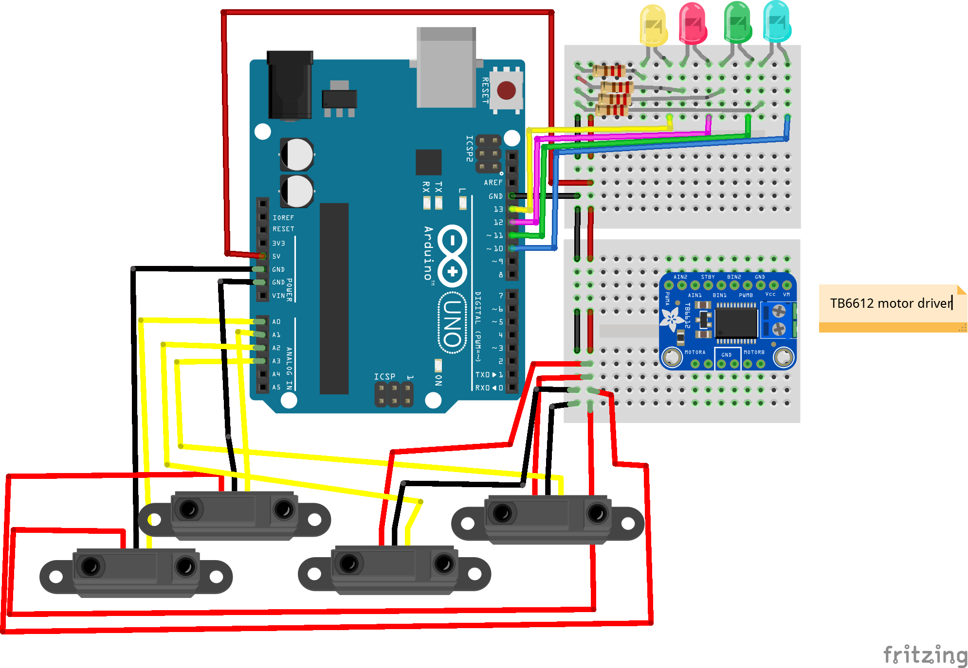
- Attach the red wire to 5V on breadboard from Arduino Uno.
- Attach the black wire to ground on breadboard from Arduino Uno
- Attach the white wire which is the analog signal to A0, A1, A2, and A3.
1 / 3
- If you have never programmed in Arduino sketch, please review the link to learn how to program using the cloud editor or IDE.
- Use code kit at the following link to use graphical programming to test that each sensor is working.
- The code generated by the graphical program to run in the Arduino IDE is shown below.
- View the video for more details on how the programs works for the short range and long range sensors.
- Note that the sample code only tests the sensor at A0.
1 / 2
int ylwLED, redLED, bluLED, grnLED;
float val, distance, volts;

// read sonar and return distance

int get_distance2() {
  val = (analogRead(A0));
  volts = val * 5;
  volts = volts / 1024;
  distance = 29.988 * Math.pow(volts, -1.173);
  distance = distance / 2.54;
  return distance;
}

// turn of all LEDs
void all_LEDS_off2() {
  digitalWrite(bluLED, LOW);
  digitalWrite(grnLED, LOW);
  digitalWrite(redLED, LOW);
  digitalWrite(ylwLED, LOW);
}

void setup() {
  pinMode(ylwLED, OUTPUT);
  pinMode(redLED, OUTPUT);
  pinMode(bluLED, OUTPUT);
  pinMode(grnLED, OUTPUT);
  ylwLED = 10;
  redLED = 11;
  bluLED = 12;
  grnLED = 13;
  pinMode(A0, INPUT);
}

void loop() {
  if ((get_distance2()) < 4) {
    digitalWrite(ylwLED, HIGH);
  } else if ((get_distance2()) < 6) {
    digitalWrite(redLED, HIGH);
  } else if ((get_distance2()) < 8) {
    digitalWrite(bluLED, HIGH);
  } else {
    digitalWrite(grnLED, HIGH);
  }
  delay(100);
  all_LEDS_off2();
  delay(100);
}
The following code was generated for the short range IR sensor.

14 projects • 23 followers
Carlotta Berry is a Professor and Dr. Lawrence J. Giacoletto Endowed Chair for Electrical and Computer Engineering at Rose-Hulman.


Comments
Please log in or sign up to comment.