


July 19 2013
Updated - July 20 2013
Video of BlinkRing
Schematics
Files and Documents
What is a BlinkRing?
The concept is simple: make a round PCB with a large hole milled out in the middle and put some LEDs and a micro-controller on it. Program a blinking party and done.
Where the idea comes from
An idea of a blinking earring was born while talking at the local hackerspace. Inger was playing with harddisk parts and wanted to make blinking earrings. She has been doing workshops making jewelry from old computer parts (very, very nice; she is not an engineer/technician).
Programming BlinkRing
Programming this little device has its own challenges. For one, the PIC12LF1552 used in this project is not supported by the PICKit2 programmer and a data-file hack was needed to get programming support working. Luckily, others have had this problem too and you can use the PICkit 2 Device Data File Editor. Unfortunately, it needs windows (so I needed to fire up a virtual machine, cross fingers, and hope for the best). It did work and programming could commence.
The second challenge in programming small designs is the complete and utter lack of "standard" ICSP programming headers. You do not want to clutter your design with bulky headers at all. You need pogo-pins.
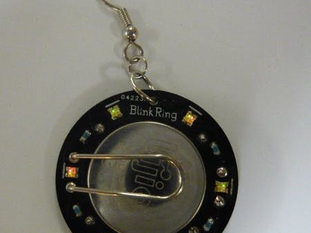
The PCB has five small exposed pads on the backside (see above). These pads are the ICSP programming pins. A small helper-board was made with a set of spring-loaded pins which can be pressed onto the PCB. Alignment can be a bit tricky, but with a little practice it works fine.
When designing a PCB that needs pogo-pins, you need to be very careful to design it in a way so that you can use a standard vero-board (or something similar). In this case, it was carefully planned to have the pads spaced at 100mil intervals, just like a vero-board. In mass-production, you will need to do a lot more thinking to enable testing and so.
Functionality is given to the device with a lot of software. The really hard part of modern electronics. There are 12 LEDs in total. Six red and six green. The red/green LEDs are in one house and spaced at 60 degree angle.
The LEDs are organised to be chariplexed, using 4 GPIO for 12 LEDs. Initial testing readily showed that the choice of series resistor was wrong (originally 470Ω). The intensity would be too low and the resistors were reduced to 100Ω. The second problem immediately apparent was the huge intensity difference between the red and green LEDs. I had chosen the LEDs based on similar specs for both red and green, but there is still a lot of difference in practice. A software solution needs handle that case.
The firmware for the device comprises a setup where all 12 LEDs are charliplexed at about 710Hz. This enables each LED to have 16 levels of intensity from off (0) to max (15) at an effective rate of ~59.2Hz. The green LEDs are activated about twice as long as the red LEDs to compensate for the difference in intensity. The processor runs at 1MHz (Fosc/4 = 250kHz).
The firmware includes tables with commands for different modes of operation. Each command says something like "set LED red/green [0-5] at level [0-15]". Pressing the button will advance to the next mode and show a new pattern. Holding the button for a second will turn the device off (same as mode 0). The processor will enter sleep when off and react to a press of the button to wake up. It is estimated that the battery will live for something between 100 and 200 hours of active operation, depending the pattern displayed. The battery should live for much more than a year when the device is kept in sleep.


Comments