One of the main driving forces in the industry for the fields of image processing and automatic control systems is the concept of an Autonomous Vehicle capable to do everything that a human driver can do and more, like automatic navigation, better environment awareness and improved safety algorithms and systems.
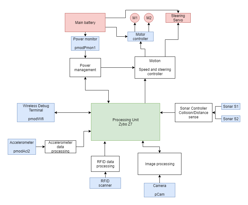
We decided to implement an autonomous vehicle on a Zybo Z7-20 platform, using a Digilent PCAM as its main camera to capture the road and road signs ahead, with an additional array of sensors including an accelerometer, a sonar and an RFID scanner to gather additional data on its course.
Our goals are to have a model car that:
- Can stay safe on the road
- Hold its lane
- Follow road signs and regulations
- Not depend on any human input for successful operation
- Hardware platform
Frame, motors and steering
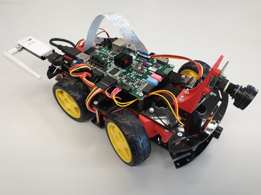
The hardware platform is built around a plastic car frame on 2 levels, with all the additional mounting hardware and supports being designed in CAD and 3D printed out of PLA plastic. The frame also includes 2 electric brushed DC motors with ample torque to power the car at a decent speed. The steering system resembles that of a go-kart (Ackerman steering), with the servo pushing one wheel hub that also transfers the motion to the second one via a pushrod. The steering system is fully 3D printed and requires minimal assembly.
The frame itself requires additional holes and mounting points as per your personal needs, depending on how you want to place the different components/sensors.
Battery and Power Supply
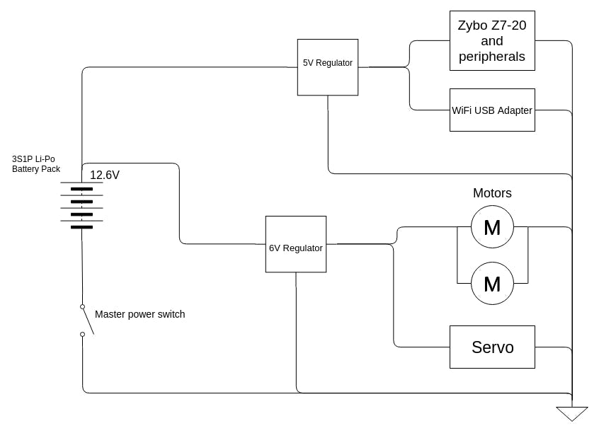
The power to all the systems on board is supplied by a Li-Po battery in a 3S1P configuration, providing 12.6V on a full charge. This is passed through 2 voltage regulators that output 6V for the servo and motors and a low-noise, low-dropoff, stable 5V to the Zybo (and its peripherals). The battery is monitored with a Li-Po voltage alarm/monitor, to prevent over-discharge.
Camera
The PCAM is mounted at the front of the vehicle, on a 3D printed stand that provides the optimal viewing angle and height. We used a fisheye lens with the original one to extend the view field, as required by the lane detection algorithm.
RFID Scanner
Under the vehicle, between the front wheels is an RFID scanner device connected via I2C to the main board that is used to detect and read RFID tags/cards/stickers on the ground to provide info to the car about the road, such as speed limits and road signs (both as a failsafe for the camera and as a secondary system, available even in bad lighting conditions).
Sonar
The sonar is placed up front, and its purpose is to detect obstacles on the road and to provide a sense of distance to the processing algorithm.
Accelerometer
The accelerometer is mounted on top of the vehicle and is used to measure the current speed of the car by periodically sampling the acceleration data in 3 axis via I2C and running an algorithm on them.
WiFi Adapter
We use a USB wifi dongle to have our car wireless for debugging purposes, tightly integrated with the Embedded Linux distribution running onboard.
We implemented 2 AXI IPs in VHDL to act as drivers for the actual custom hardware on the car, namely the motors&servo and the sonar.
The motor driver has hardware enable/disable switches (for failsafe and safety), as well as register controlled ones, and exposing the base hardware (the actual Pololu motor driver and the servo itself) as writeable registers (everything is PWM driven in the end, so the registers command an array of variable-frequency variable-resolution PWM drivers designed in VHDL).
The sonar driver is based on the Pmod MAXXSONAR IP, it is a PWM signal counter.
Video pipeline
The video pipeline is based on the PCAM demo from Digilent. We modified the AXI Bayer-to-rgb IP to output pixels in the 8 bit/channel, 3 color channels format (24 bit per pixel) and we removed the output stream (M2SS) component and HDMI output. The Omnivision OV5640 camera is controlled via I2C from userspace, being configured as per its datasheet available online.
The project is centered around an Embedded Linux distribution from Xilinx, Petalinux 2017.4. We decided to go this route because our project includes many different modules (both hardware and software), and the Linux OS acts as a common ground between them, managing the processes and providing debug tools, persistent memory on the SD card, SSH access etc.
The Linux distribution runs a highly modified kernel that is adapted to our needs and provides support for the physical devices (camera, sonar, motors and servo) via custom kernel modules (device drivers) and support for the WiFi adapter via a modified USB driver based on the TP-Link driver available online. Xilinx already included drivers for Zynq I2C, used to connect with the camera and other devices.
We included a diverse set of testing apps, basically used to unit-test the different modules, before integrating them fully with the main OpenCV app that manages the whole process.
Kernel modules
There are 4 custom kernel modules integrated with the board, that manage specific hardware components, interacting with the VHDL AXI IPs connected to the Zynq processing core.
- Videodriver: provides basic /dev/video access to the VDMA framebuffers to read the stored images as quickly as possible, minimizing memory transfers. It also provides ioctl access to different setup parameters to correctly configure the userspace applications.
- Motiondriver: provides /dev/motors and /dev/servo write access to userspace apps and manages these devices, displaying an easy to use API for controlling the motors and steering of the car
- Sonardriver: provides read access to /dev/sonar to userspace apps to easily read the distance reported by the sonar.
- 8188eu updated driver for the WN722N TP-Link USB WiFi device, ported from kernel 4.3 to 4.9 and adapted for continuous usage, with minimal power saving functions to limit overhead.
The control of the car is composed of the OpenCV module which processes the image from each frame and sets corresponding flags and variables for the Car control module to take actions accordingly.
OpenCV module
The flow of image processing is split into in two parts, each running on its own thread. One thread controls the lane detection and includes the car control algorithm and the other is constantly detecting signs.
- Lane detection component:
The Pcam 5C camera provides a 720p image with the closest part of the lanes being in focus as it is the most important part of knowing how to control the steering of the car.
The 720p image is resized to half its size to aid processing, and from now on all the images used in the lane detection component will be 360p.
resize(image_read, frame, cv::Size(), 0.5f, 0.5f);
Most of the image processing is done in grayscale so the next step is to convert the resized image from RGB to grayscale.
cvtColor(frame, gray_image, CV_RGB2GRAY);
For the edge detection part of the process we need to blur the image so the Canny method won't detect small, insignificant edges and only take in the big important ones.
GaussianBlur(gray_image, blurred_image, Size(5, 5), 0, 0);
After the preprocessing is done the main computer vision part is started.
The Canny method returns the important edges from the image, as intended, which will be used later to detect the position of the lines in relation to the car.
Canny(blurred_image, canny_image, 50, 150);
To process just some relevant parts of the canny result we need to apply a mask on the canny image. Said mask is made from an empty image on which the regions of interest are white, we do this with the function lines.
mask = cv::Mat::zeros(frame.size(), canny_image.type());
lines(mask);
After the bitwise_and the resulted image(ROI_image) contains just the points on the line that will later be used in the steering control part of the program.
bitwise_and(mask, canny_image, ROI_image);
- Stop sign detection component:
The stop sign detection preprocessing is the same as the lane detection preprocessing, with the mention that only the right part of the image is processed (we only considered the right part of the image as the real life signs are mostly to the right side of the road, for left side driving conditions the crop function can be changed to update to the conditions set).
The thread in charge of the stop sign detection waits to have an available image from the camera and calls the detect_and_display function which returns 1 if a sign is considered to be in the vicinity of the car and 0 otherwise.
stop_sign = detect_and_display(image, param);
Because the field of view of the camera is somewhat reduced we can't evaluate how close the car is to the sign (as in a normal situation when you would stop next to a stop sign) so the car stops when it has seen a stop sign in the last processed image and said stop sign exits its field of view in the current processed image.
Car control part:
The ROI_image is sent to the servo control algorithm which returns the corresponding servo value for the lines detected. This is done with the function servo_comand_line.
servo_out = servo_comand_line(ROI_image, frame, param, new_speed);
The function returns a servo value in the working range of the servo motor, this value is adjusted with the speed of the car, like in the real life situation when the car is driving faster, so the steering needs to turn less for the same movement. If the function encounters a bad data, meaning a broken lane line or a faulty image the function will return -1 signaling to the next piece of the control part to keep the same turn angle.
The speed of the car is computed in several steps:
Firstly, determining if the car can advance or not, using the sonar(reading /dev/sonar).
read(sonar->_fileno, &clk_edges, 4);
dist = clk_edges * clk_to_cm;
Secondly, the car checks for stop signs, using the stop_sign flag that was set in the stop sign detection part of the control process.
if (stop_sgn == 0 && old_stop_sgn == 1) {
    //STOP THE CAR
}
Lastly, the car reads RFID cards, if there are any under the car it executes the specific action of the card, being speed up, slow down or halting.
card_now = popCard(c_queue);
if (card_now != NULL) {
	switch (card_now->type) {
            //CASE FOR EACH TYPE OF CARD
        }
}
If none of these steps are met the car continues its drive with the last set parameters.
After the servo and speed parameters are correct they are transmitted to the kernel modules (via /dev/servo and /dev/motors) so the computed action is executed.
write(motors->_fileno, &speed, 4);
write(servo->_fileno, &servo_out, 2);
Get relevant images
Because humans aren't as good with numbers as computers we need to add the relevant information on screen.


Comments
Please log in or sign up to comment.