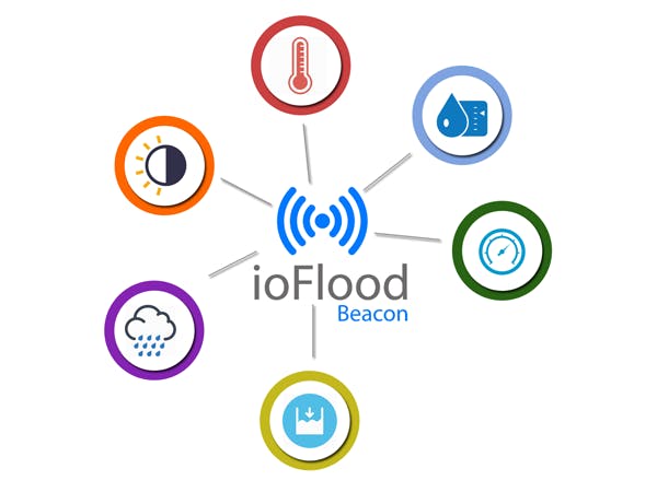
Sparkfun Artemis ATP RedBoard, Sparkfun sensor breakout boards and Sparkfun Qwiic echo system are the de facto for IoT world. No soldering is needed, simply daisy chain them. That's it everything is working like a charm. My project is a flood water disaster warning system called ioFloodBeacon with few components and with low cost. Apart from the warning system, this can be worked as a miniature terrestrial weather station to collect environmental data such as temperature, humidity, air pressure, ambient light, Co2 level.
I am going through the entire project development in step by step fashion because this is a quite big project.
Getting environment readyBefore you proceed with the rest of this guide, make sure you have necessary software and libraries are installed.
Install Arduino IDE, click here.
Add Sparkfun Artemis ATP red board to Arduino IDE, the information is here.
Need to add following libraries in order to work with sensors.
Sparkfun CCS811/BME280 environmental combo - click here
Sparkfun VCNL4040 proximity sensor - click here
Sparkfun Micro OLED - click here
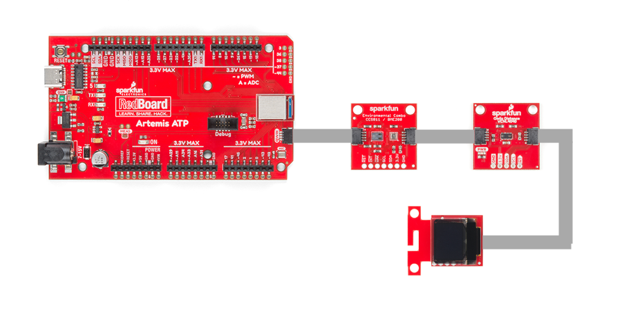
Connecting sensorsDaisy chain all the components. Connect the Artemis board to the computer using USB cable and upload below code.
#include <stdint.h>
#include "SparkFunBME280.h"
#include "Wire.h"
#include "SPI.h"
#include "SparkFun_VCNL4040_Arduino_Library.h"
#include <SFE_MicroOLED.h>
#define PIN_RESET 9
#define DC_JUMPER 1
BME280 mySensor;
VCNL4040 proximitySensor;
MicroOLED oled(PIN_RESET, DC_JUMPER);
void setup() {
mySensor.settings.commInterface = I2C_MODE;
mySensor.settings.I2CAddress = 0x77;
mySensor.settings.runMode = 3;
mySensor.settings.tStandby = 0;
mySensor.settings.filter = 0;
mySensor.settings.tempOverSample = 1;
mySensor.settings.pressOverSample = 1;
mySensor.settings.humidOverSample = 1;
Serial.begin(9600);
Serial.print("Starting BME280... result of .begin(): 0x");
Serial.println(mySensor.begin(), HEX);
Wire.begin();
if (proximitySensor.begin() == false)
{
Serial.println("Device not found. Please check wiring.");
while (1);
}
oled.begin();
oled.clear(ALL);
oled.display();
delay(1000);
oled.clear(PAGE);
}
void loop() {
printTitle("Pressure : " + String(mySensor.readFloatPressure()) + "kPa" ,1);
delay(2000);
printTitle("Temperature : " + String(mySensor.readTempC()) + "C",1);
delay(2000);
printTitle("Altitude : " + String(mySensor.readFloatAltitudeMeters()) + "m" ,1);
delay(2000);
printTitle("Humidity : " + String(mySensor.readFloatHumidity()) + "%",1);
delay(2000);
}
void printTitle(String title, int font)
{
int middleX = oled.getLCDWidth() / 2;
int middleY = oled.getLCDHeight() / 2;
oled.clear(PAGE);
oled.setFontType(font);
oled.setCursor(0,0);
oled.print(title);
oled.display();
delay(1500);
oled.clear(PAGE);
}
void proximity(){
unsigned int proxValue = proximitySensor.getProximity();
Serial.print("Proximity Value: ");
Serial.print(proxValue);
Serial.println();
printTitle("Proximity : " + String(proxValue),1);
delay(10);
}
If everything goes well, you will see the below output as show in the video below.
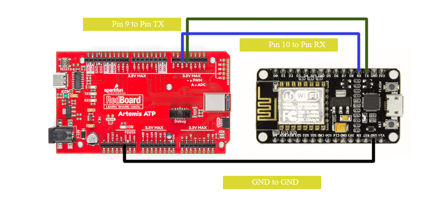
Connecting to IoT gatewayI planned to use SIM800/900 with the project for data communication with my web socket server but my SIM800 had some problem when connecting with the ISP. So I decided to use ESP8266 as an IoT gateway. ESP8266 will receive the sensor data from Artemis via serial connection then ESP8266 will send sensor data to my web socket server. Follow the diagram for how the wiring need to be done. The following code provide the serial communication between two boards.
#include <SoftwareSerial.h>
SoftwareSerial esp8266(9,10);

void setup()
{
    esp8266.begin(9600);
}

void loop()
{
    esp8266.print(proxValue);
    esp8266.print(",");
    esp8266.print(mySensor.readTempC());
    esp8266.print(",");
    esp8266.print(mySensor.readFloatHumidity());
    esp8266.print(",");
    esp8266.print(round(mySensor.readFloatPressure()));
    esp8266.print("\r\n");
    delay(1000);
}The purpose of the IoT gateway is to collect data from the devices and transmit to the web socket. The following code need to be uploaded to the ESP8266.
#include <WebSocketsClient.h>
#include <ESP8266WiFi.h>
#include <ESP8266WiFiMulti.h>
ESP8266WiFiMulti WiFiMulti;
WebSocketsClient webSocket;
bool isConnected = false;
int SENSOR_ID = 1;
String distance = "0";
String temp = "0";
String humidity = "0";
String bp = "0";
int rain = 0;
int light = 0;
String incomingByte = "";
int i1, i2, i3, i4;
void webSocketEvent(WStype_t type, uint8_t * payload, size_t length) {
switch(type) {
case WStype_DISCONNECTED:
isConnected = false;
break;
case WStype_CONNECTED:
{
isConnected = true;
webSocket.sendTXT("5");
}
break;
case WStype_TEXT:
break;
case WStype_BIN:
hexdump(payload, length);
break;
}
}
void setup() {
Serial.begin(9600);
for(uint8_t t = 4; t > 0; t--) {
delay(1000);
}
WiFiMulti.addAP("SSID", "password");
while(WiFiMulti.run() != WL_CONNECTED) {
delay(100);
}
webSocket.beginSocketIO("web-socket-ip", port);
webSocket.onEvent(webSocketEvent);
}
void loop() {
webSocket.loop();
if(isConnected)
{
if(Serial.available()>0){
incomingByte = Serial.readStringUntil('\r\n');
Serial.println(incomingByte);
i1 = incomingByte.indexOf(",");
distance = incomingByte.substring(0,i1);
i2 = incomingByte.indexOf(",", i1+1);
temp = incomingByte.substring(i1+1, i2);
i3 = incomingByte.indexOf(",", i2+1);
humidity = incomingByte.substring(i2+1, i3);
i4 = incomingByte.indexOf(",", i3+1);
bp = incomingByte.substring(i3+1);
rain = 1;
light = 1;
webSocket.sendTXT("42[\"beacon\",{\"id\":" + String(SENSOR_ID) + ",\"name\":\"deduru oya\",\"value\":" + distance + ",\"temp\":" + temp + ",\"humidity\":" + humidity + ",\"rain\":" + String(rain) + ",\"air\":" + bp + ",\"light\":" + String(light) +"}]");
}
}
}
This is a custom made web socket by me using socket.io.
Finally, data visualizationMy web socket listen for a specific event call "beacon" and once the event fired it grab all the data from the channel then the data will be written to the MongoDB. Simultaneously my web application and mobile application are also listing for the above event and get updated their UI.
Check out the web application here.
The mobile app is here.
Check out the video here.
How we can mitigate the flood water disaster using this system?Using the web application and mobile application users can determine the water level of the lake, tank or river. So before the overflow happened they can evacuate the place. This system is very economical and easily develop with few components and save millions of people lives. This device is suppose to fix in the place where we can take measure of the water level. The device will be powered by a battery and battery is regularly charged by a solar panel. The data communication should be done by a GSM/3G/4G/NBIoT or 5G modem.
The proximity sensor is used for this project is not very accurate and SparkFun VL53L1X sensor may be the ideal solution. Apart from that we can plug more sensors to read other environment related data such as wind speed, wind direction and rain gauge. SparkFun Weather Meter Kit will be a great solution for those sensors.
At last not least "Machine Learning in Real World"This is the essence of the project and the ultimate goal of the Artemis board ML in real world. Here I have created a small model call rain fall detection, the model will be able to predict whether it's going to be rain or not by using current temperature, humidity and barometric pressure. You can find the Google colab notebook file here. The training dataset I got from Kaggle austin weather dataset. Here, you can find the modified dataset I used to train the model here.
Follow my github for entire project code.
Check out the video here.


_3u05Tpwasz.png?auto=compress%2Cformat&w=40&h=40&fit=fillmax&bg=fff&dpr=2)

Comments