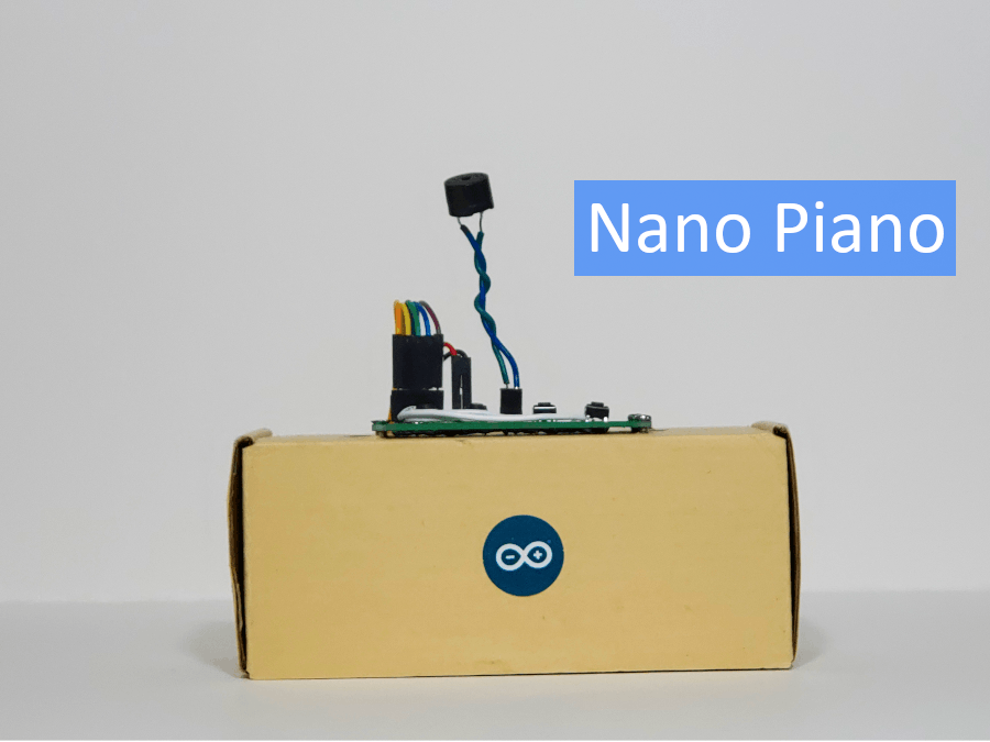
Nano Piano is a four key piano that runs off of an Arduino Nano Every. This project is beginner friendly, and it is great if you are looking to get into Arduino or electronics as a whole. I will be going over everything you need to know to create this project. You get to decide how its assembled but I will be showing you all the electronics and things you need to make it work.
Step One: Choose your Construction BaseA construction base is essentially how you connect all the components. A few big examples are perf board (also called proto board) and breadboard. I personally used perf board but you can decide what you want to use, remember that perf board does require a soldering tool to be used properly.
Step Two: Housing the ElectronicsIt is not exactly required to house the electronics but it is nice to do. If you have a 3d printer I would recommend creating a proper 3d print to house the electronics but if you are like me and do not currently have a 3d printer, I would recommend using cardboard or something easy to manipulate that can hold the electronics.
Before we build the piano, you need to upload the program to the Arduino. For this you will need to install Arduino IDE which has support for Windows 10, Linux, and MacOS X. If you are not able to install Arduino IDE you can use the web editor to upload the code. Once you have your IDE situated, you can now proceed to upload the code below.
/*
Nano Piano
A simple, small piano that uses the Arduino Nano Every.
created 2/25/2021
by Christian Madlansacay
GitHub: https://github.com/Christian-Madlansacay
Hacksterio: https://www.hackster.io/christian-madlansacay
Instagram: https://www.instagram.com/c_madlansacay/
Twitter: https://twitter.com/c_madlansacay
YouTube: https://www.youtube.com/channel/UCSJFVhXUiDDvXZKhmj4Wijg
https://www.hackster.io/christian-madlansacay/nano-piano-8da96d
*/
// Customize the frequency values for each note (Note: It is not possible to generate tones lower than 31Hz.).
int noteOneFreq = 170;
int noteTwoFreq = 180;
int noteThreeFreq = 190;
int noteFourFreq = 200;
// Variables for each of the digital pins for components.
const int noteOne = 2;
const int noteTwo = 3;
const int noteThree = 4;
const int noteFour = 5;
const int passiveBuzzer = 6;
// Variables set to a default value.
int noteOneState = false;
int noteTwoState = false;
int noteThreeState = false;
int noteFourState = false;
void setup() {
// Setting INPUT pins.
pinMode(noteOne, INPUT);
pinMode(noteTwo, INPUT);
pinMode(noteThree, INPUT);
pinMode(noteFour, INPUT);
// Setting OUTPUT pins.
pinMode(passiveBuzzer, OUTPUT);
}
void loop() {
// Creating variables to read the state of each of the INPUT pins.
noteOneState = digitalRead(noteOne);
noteTwoState = digitalRead(noteTwo);
noteThreeState = digitalRead(noteThree);
noteFourState = digitalRead(noteFour);
if (noteOneState == HIGH) {   // Checks if note state is sending a HIGH signal.
tone(passiveBuzzer, noteOneFreq);   // Sends a frequency value to the passive buzzer according to which button is pressed.
} else if (noteTwoState == HIGH) {   // Repeats.
tone(passiveBuzzer, noteTwoFreq);
} else if (noteThreeState == HIGH) {
tone(passiveBuzzer, noteThreeFreq);
} else if (noteFourState == HIGH) {
tone(passiveBuzzer, noteFourFreq);
} else
noTone(passiveBuzzer);   // If none of the notes are sending a HIGH signal send noTone to the passive buzzer.
}
This code can also be found at the designated GitHub repository. If you are having issues or are not familiar with the IDE, you can see a starter tutorial here.
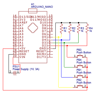
Step Four: AssembleTo assemble this project, your gonna need to gather all your components and get to work. If you are not familiar with reading schematics I would highly recommend checking out this post from Sparkfun on how to read a schematic. Down below is the schematic you need to follow to complete the project.
I have also made a project on EasyEDA where you can also find this schematic. For those of you wondering how it works, I am not going to really be going over that but I recommend you look at this Arduino article on how to use buttons with Arduino. Once you have finished putting together the electronics, now is a good time to plug it in and test it. If it does not seem to be working, please comment on this post and I will try my best to reply. If you are not given help you should definitely look at the Arduino troubleshooting page for assistance. If it does work, then good job. You can now house all the electronics in whatever housing you created or you can just leave it how it is. I personally put one perf board with the buttons and buzzer on the top of my box and put another perf board with the Arduino and resistors inside of the box.
If you have made it all the way here, congratulations you are at the end. This is my first Hacksterio post, and if you have any suggestions on more projects I should do in the future, please comment them. Anyway thank you for checking out my project and I will be making more soon.
Need Help?Feel free to comment down below to get help from me or anyone else who may have a solution to your issue!
SocialsGitHub: https://github.com/Christian-Madlansacay
Hacksterio: https://www.hackster.io/christian-madlansacay
Instagram: https://www.instagram.com/c_madlansacay/
Twitter: https://twitter.com/c_madlansacay
YouTube: https://www.youtube.com/channel/UCSJFVhXUiDDvXZKhmj4Wijg


_3u05Tpwasz.png?auto=compress%2Cformat&w=40&h=40&fit=fillmax&bg=fff&dpr=2)
Comments
Please log in or sign up to comment.