


Software apps and online services | ||||||
.png?auto=compress%2Cformat&w=48&h=48&fit=fill&bg=ffffff) |
| |||||
| ||||||
 |
| |||||
Hand tools and fabrication machines | ||||||
 |
| |||||
 |
| |||||
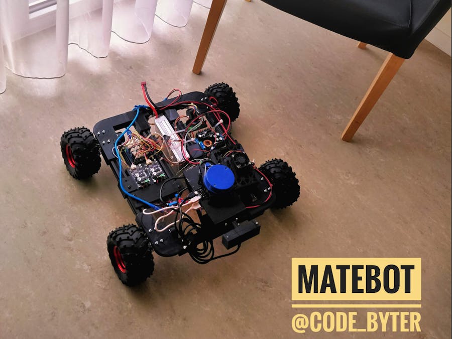
I love Argentinian Mate tea and robotics, so why not combine both? The robot is supposed to drive around autonomously in my room and create a map of it. Once the robot spots a mate teacup, it marks the spot on the map and sends a notification to a phone.
One of the most reliable ways to create an indoor map is to use a Lidar. That’s a sensor that measures the distance to a target by illuminating the target with laser light and measuring the reflected light. By rotating the sensor, the whole surrounding environment is captured.
The mate teacup will be detected by a camera using computer vision and machine learning. For this robot, I’m using a stereo camera, so it’s even possible to extract the depth information from the image
To process the sensor data and the actuator signals, I’m using the open-source middleware ROS (Robot Operating System). Click here to learn more about ROS.
2. Parts- YDLidar X4: This is a cheap 360° Lidar with a range of ~10m
- ELP 3D Stereo Camera
- Pololu 19:1 Metal Gearmotor 37Dx68L mm with 64 CPR Encoder: These motors have built-in encoders. An encoder can measure the rotation. Those can measure up to 1200 steps per revolution
- Motor mounts
- Four MD13S Motor drivers: The Arduino can't provide enough power for the motors, so dedicated Motor drivers are needed
- Arduino Uno: This one will be used to control the motors and count the steps of the encoders
- Arduino Uno Groove Shield
- Dagu Wild Thumper Wheels with Connectors
- Six 250mm 2020 aluminium profiles
- Step-Down USB module
- Nvidia Jetson Nano: This is the brain of Matebot. It runs on Ubuntu, so ROS works on it. And it's perfect for computer vision
- 4s (14.8V) Lipo battery
- 64 GB micro SD card
- Two step down converter
The frame consists of four corner pieces — Mount the motors and aluminum profiles to them. The middle profiles need the T and H brackets. All the power electronics are mounted to them. You can find all the printable.stl-files here
4. Assembling MateBotYou can see the main structure of MateBot in the following scheme. First, assemble the frame with the aluminum profiles and motors. Next, we need to mount the components. Every component has a corresponding printable mount so that you can mount it directly to the aluminum profile.
The following table describes the wire functions of the motor:
The motor power pins are connected to the MD13S motor drivers. Those have a DIR and PWM pins each. Be careful! You can only connect the PWM Pins to a PWM capable Arduino Pin (Digital Pin 3, 5, 6, 9, 10, 11). I used the following configuration:
Connect the encoder power pins to the corresponding Arduino pins and the encoder data pins to the remaining Arduino pins.
The Motor drivers have an input voltage of 12V. The step-down modules have two potentiometers — one for limiting the voltage and one for the current. Change the first potentiometer position, so the output voltage is 12V. Then connect the motor drivers.
For the second step-down converter, set the output voltage to 5V and connect the NVIDIA Jetson Nano.
The Lidar has two micro USB ports. One for data and one for power. Connect the USB charger module to the battery and power the Lidar with a micro-USB cable.
I will write a second tutorial on installing ROS and the required nodes. But if you want to test the hardware setup, here’s some sample code. But first, you need to install this Arduino library
#include "CytronMotorDriver.h"// Configure the motor driver.CytronMD motor1(PWM_DIR, 3, 2);  // 1PWM = Pin 3, 2DIR = Pin 4.CytronMD motor2(PWM_DIR, 5, 4);  // PWM = Pin 3, DIR = Pin 4.CytronMD motor3(PWM_DIR, 9, 8);  // PWM = Pin 3, DIR = Pin 4.CytronMD motor4(PWM_DIR, 6, 7);  // PWM = Pin 3, DIR = Pin 4.void setup() {}void loop() {    motor1.setSpeed(150);  // Run forward   motor2.setSpeed(150);  // Run forward   motor3.setSpeed(150);  // Run forward   motor4.setSpeed(150);  // Run forward   delay(2000);  motor1.setSpeed(0);     motor2.setSpeed(0);   motor3.setSpeed(0);   motor4.setSpeed(0);   delay(3000);
}
If you want to test the motor encoders, I recommend you to check out this tutorial
6. Future workIn the next tutorial, we will install Ubuntu and ROS on the Nvidia Jetson Nano. Then you’ll learn how to build a ROS node to control the motors. For the Lidar and stereo Camera, we’ll install the corresponding node and use the Hector Slam algorithm to create a map of the room.
If you are interested in the current progress, check out my Instagram (@code_byter) and GitHub (code-byter) page.


Comments
Please log in or sign up to comment.