This project describes system optimization for LoRa Node operation in LoRa Point-to-Point Network Communication. The current issue is that LoRa cannot reach more than 2 kilometers due to heavy interference when deployed in dense areas such as cities. Furthermore, most off-the-shelf LoRa Nodes are power-hungry and would not be able to last more than 3 days on battery power. The goal of this study is to use two optimization methods and evaluate the Node Operation after implementing those methods. The first is the RTOS method which is the Deep Sleep for reducing the LoRa Sensor Node power consumption and adding another LoRa Node as an intermediate Node to increase network transmission distance.
The Problem Statement
- LoRa cannot reach more than 2 kilometers due to heavy interference when deployed in dense areas such as cities
- most off-the-shelf LoRa Nodes are power-hungry and would not be able to last more than 3 days on battery power
The Objective
- To increase the LoRa Transmission Range, add another LoRa Node to act as the Intermediate Node.
- Deep sleep is used to conserve and reduce LoRa Node power consumption.
TheProject Block Diagram
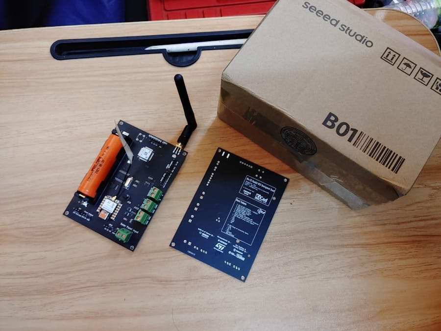
The Wio-E5 Parallel MCU Board Setup
Designed By Me! Manufactured by Seeed Studio. Thanks to their Seeed Fusion Service the Excellent quality of PCB Manufacturing and Craftmanship! Really love it!
The Board contains the following chip and modules I use from Seeed Studio.
- Seeed Wio-E5 module: https://www.seeedstudio.com/LoRa-E5-Wireless-Module-p-4745.html2.
- Seeed XIAO ESP32C3 mcu: https://www.seeedstudio.com/Seeed-XIAO-ESP32C3-p-5431.html3.
The Board Design is later I get it to be manufactured using Seeed Fusion Service! Do Check them out!
- Seeed Fusion PCB Assembly Service: https://www.seeedstudio.com/pcb-assembly.html
The Board Casing View
This is my LoRa Sensor Node or the Sender Setup, notice the White Box contains The Wio-E5 + ESP32 Development Board and the Black Box contains 3 types of sensors. The sensor I use are :-
- MQ-135 Air Quality Sensor
- DHT11 Sensor
- LDR Module Sensor
How do I validate the Test?
I use the Digital Multimeter to measure the Power Consumption. I set the Multimeter to Current mode and measure each of the Sensor's Current values. The Board Current is based on the Datasheet to which I refer.
Results and Data AnalysisFollowing the implementation of the proposed method, the LoRa Sensor Node proved to produce a different result.
The Field Testing for LoRa Transmission Range Measurement.
The first test is performed between the Sender and the Receiver. The Receiver is linked to the internet via the cellular network of my phone. While the LoRa Communication is active, it is able to receive data from the Sender. The field test demonstrated that the pair communication can travel as far as 2.20 kilometers, which is impressive given that the test site is in a suburban area.
Later on, I add another LoRa board, my Wio-E5 Parallel MCU Development Board, which serves as the Intermediate Node or the Middle Man between the Sender and the Receiver. Previously I was able to get 2.20 Kilometers now with the Intermediate Node I am able to get up to 3.7 kilometers.
Node-RED Flow Setup
Data Visualization using FAVORIOT
This is the Dashboard view. I'm using FAVORIOT, A Developer Friendly IoT Middleware with rich features for Developers to customize.
LoRa Sensor Node Power Consumption Measurement.
For power consumption, I use a multimeter to measure the currents of the Board and the sensor. Here is the outcome of my 1-hour measurement. The battery I'm using has a capacity of 2000mAh and is an 18650 Li-Ion battery.
Following field testing, both proposed methods have increased the LoRa transmission range and reduced the LoRa sensor node power consumption. The transmission range of P2P is only 2.2 kilometers, but with an Intermediate Node, it can reach 3.7 kilometers, a 1.5- kilometer increase. The LoRa Sensor Node with Battery Powered can last 2.45 times longer with Deep Sleep Configuration compared to the default configuration.


Comments
Please log in or sign up to comment.