


Hardware components | ||||||
| × | 1 | ||||
| × | 1 | ||||
| × | 1 | ||||
Software apps and online services | ||||||
| ||||||
| ||||||
 |
| |||||
Open the AE-CLOUD1 kit.
Take out the debugger, all three cables, and the main blue board. We will not use the WiFi module in this project (yet).
Connect The HardwareConnect it to the JTAG connector of the board and the debugger. Connect the board to USB Power.
Plug the debugger into your computer. Your computer will now have two USB cables plugged into it.
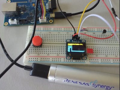
Connect the Grove cable to the Grove connector closest to the PMOD or USB connector. It will say, *I2C* on it.
Plug your LCD module into a breadboard or connect the Grove cable directly to the pins. Your module will be black at this stage.
- Grove pin 1 is SCL on LCD panel, yellow, serial clock
- Grove pin 2 is SDA on LCD, data, white
- Pin 3 is VCC, power, red
- Pin 4 is GND, ground, black
Flash the board with a pre-compiled binary to test the LCD module and ENS210 onboard environmental sensor.
Start up J-Flash Lite. Select Renesas R7FS5D97E as the device.
Select SWD as the Interface.
Speed is not critical. Using 4000 is safe.
Download the file OLED.srec from GitHub releases. Select the file in J-Flash Lite.
Program the device.
Reboot your board by pulling the USB power cable out and plugging it back in. You will see the default screen, which is a monochrome bitmap stored into the program as a c array. You can edit this later with the source code on GitHub. For now, let's review the screen to make sure your wiring works.
You will see text screens that you can also edit.
Currently, the project is not pushing sensor data to the cloud. In the future, I hope to add this in. I've based my project on the GitHub repo project from Mike Li. Thanks Mike. :-)
You will see the temperature displayed from the onboard environmental sensors.
To customize the binary, you will need Renesas e2 Studio and Synergy. This is a free download for non-commercial use.
- Synergy Software Package (SSP) 1.3.0 (scroll down to archived versions)
You will also need the Board Support Package (BSP) and the finished package.
Download all the files from GitHub. Copy the file Renesas.S5D9_IOT_BOARD.1.3.0.pack into this folder
C:\Renesas\e2_studio\internal\projectgen\arm
Extract the file finished-oled-archive.zip
e2 StudioImport the files into e2 Studio. Compile. The .srec file will be in the Debug folder.
Under src, select the file hal_entry.c.
Use the search feature to find the string that displays on your OLED screen. For example, search for AE-CLOUD2. Edit the text string. Use only upper case letters.
After editing the strings. Compile the code and install the new binary with J-Flash Lite.
You can also change the delay in milliseconds between screens or add a third text screen.
To change the startup image, you will need to create a bitmap monochrome image with a max size of 128x64 pixels.
You can use Paint on Windows to save as Monochrome Bitmap.
Once you have a monochrome bitmap, you need to convert the bitmap into a c array. I'm using the free tool LCD Assistant for this.
The c array will look something like this:
Back in e2 Studio, change the existing array in ssd1306_oled.c to your new array.
Recompile and transfer to your board.
HelpIf you have any questions, ask on the community forum.


Comments
Please log in or sign up to comment.