


Hardware components | ||||||
 |
| × | 1 | |||
Software apps and online services | ||||||
| ||||||
| ||||||
- Part 1: Straight to the Finish Line
- Part 2: Customize our Core (you are here)
- Part 3: Creating an IP Core Manually
- Part 4: Raw AXI Streams
- Part 5: AXI Video Streams
In the last part, we created a core and demonstrated it on the Pynq Board. We could read the 'Version' register and read and write the 'Control' register. In this part, we are going to focus on how to modify a core. We'll add a new register to read/write from/to. We will use Cocotb to exercise this new register. Then we will demonstrate these new features on the Pynq board.
At a high levelWe will do the following:
- Create a new core
- Exercise the core with Cocotb
- Add a new register to our core
- Generate an IP core and update the Vivado Pynq project
- Demonstrate the core on the Pynq Board
Similar to the last part, we will create a new IP core. Move into the base directory of the 'ip-cores' repo
cd <ip-cores repository>run the following, this will generate a new IP core with the name 'demo_part2'
./scripts/new-ip-core.sh demo_part2Navigate to the 'demo_part2' directory:
cd <ip-cores repository>/cores/demo_part2listing the content of the 'hdl' directory we get:
axi_defines.v axi_lite_slave.v demo_part2.vThe 'axi_lite_slave.v' and 'axi_defines.v' are files used to convert the AXI Lite signals to a simpler interface used by 'demo_part2.v'. We can ignore these for now.
'demo_part2.v' is the main interface for our core. The crux of this module is the addresses and main synchronous block shown below.
//AXI4 Addresses

localparam  REG_CONTROL      = 0 << 2;
localparam  REG_VERSION      = 1 << 2;
localparam  MAX_ADDR = REG_VERSION;

...

//synchronous logic
always @ (posedge i_axi_clk) begin
  //De-assert
  r_reg_in_ack                            <=  0;
  r_reg_out_rdy                           <=  0;
  r_reg_invalid_addr                      <=  0;

  if (w_axi_rst) begin
    r_reg_out_data                        <=  0;

    //Reset the temporary Data
    r_control                             <=  0;
  end
  else begin
    if (w_reg_in_rdy) begin
      //From master
      case (w_reg_address)
        REG_CONTROL: begin
          r_control                       <=  w_reg_in_data;
        end
        REG_VERSION: begin
        end
        default: begin
          r_reg_invalid_addr              <= 1;
        end
      endcase
      r_reg_in_ack                        <= 1;
    end
    else if (w_reg_out_req) begin
      //To master
      case (w_reg_address)
        REG_CONTROL: begin
          r_reg_out_data                  <= r_control;
        end
        REG_VERSION: begin
          r_reg_out_data                  <= w_version;
        end
        default: begin
          //Unknown address
          r_reg_out_data                  <= 32'h00;
          r_reg_invalid_addr              <= 1;
        end
      endcase
      r_reg_out_rdy                       <= 1;
    end
  end
end
Instead of controlling the various signals of theAXI bus directly, users communicate with the host using this one synchronous process.
I've written detailed instructions on how to send and receive data to/from the core but have moved it to the Appendix B section, in short:
- To send data to the core add a new case within the 'From master' section
- To receive data from the core add a new case to the 'To master' section.
To simulate and debug the core move into the 'tests' directory
cd <ip-cores repository>/cores/demo_part2/testsThe directory contains the following files:
axi_driver.py demo_part2_driver.py Makefile tb_axi_lite_slave.v test_dut.py waveforms.gtkwThe files are as follows:
- tb_axi_lite_slave.v: The Verilog test bench that glues our core (DUT) to the 'Cocotb' simulation interface. Note: It is still possible to add simulation-only Verilog here.
- axi_driver.py: This has the low-level AXI interface signals we can safely ignore.
- waveforms.gtkw: A GTK waveform save file that formats the GTK waveform viewer with a default layout. This can be seen above.
- demo_part2_driver.py: One of the two files we will modify the most. This is the API to our core. Instead of the user writing to address 0x00 to write to the control register, we create functions like 'set_control' and 'get_control' in here.
- test_dut.py: Here is where we write our tests to simulate our core. Our goal is to test our core through all permutations ironing out as many bugs as we can before it goes on real hardware. The tests may seem intimidating at first but after you learn to parse them they are quite simple.
- Makefile: A simple makefile used to build, simulate and start the waveform viewer. The only time we will need to modify this file is to add new Verilog modules to build, See Appendix A for an example of how to do this.
Now we know the files we can simulate the core, within the 'tests' directory run 'make' and we should see an output that will report the status of the tests including debug messages that can be sent when the test is run. In the end, a summary of the results will be displayed.
test_dut.test_read_version     PASS
test_dut.test_write_control    PASS
test_dut.test_read_control     PASS
This is an excerpt of the results, the actual output is more verbose.
As you can see we ran three tests. 'read_version', 'write_control', and 'read_control'.
The Makefile will run the tests within the 'test_dut.py' going through the 'test_read_control' we can see the following:
@cocotb.test(skip = False)
async def test_read_control(dut):
    """
    Description:
        -Inject a value into the control register directly using Cocotb
        -Use the AXI interface to read the value of the control register
        -Verify the value that was read using AXI is the same as the
        value injected

    Test ID: 2

    Expected Results:
        The value read using AXI interface is the same as the value injected
    """
    dut._log.setLevel(logging.WARNING)
    dut.test_id <= 2
    setup_dut(dut)
    driver = demo_part2Driver(dut, dut.clk, dut.rst, CLK_PERIOD, name="aximl", debug=False)
    await reset_dut(dut)

    my_control = 0xFEDCBA98
    dut.dut.r_control.value = my_control
    control = await driver.get_control()
    dut._log.info ("Control: 0x%08X" % control)
    await Timer(CLK_PERIOD * 20)
    dut._log.info("Done")
    assert control == my_control
Going through this:
dut._log.setLevel(logging.WARNING)This cuts down on the number of messages that are outputted while the test is running.
dut.test_id <= 2Sets the 'test_id' to 2, this is helpful when viewing the waveforms.
setup_dut(dut)Run anything that is needed before running any tests, I usually have this inserted at the beginning of every test. This may be something like asserting an enable signal and/or starting clocks.
driver = demo_part2Driver(dut, dut.clk, dut.rst, CLK_PERIOD, name="aximl", debug=False)Instantiate our 'demo_part2Driver' core we will use to test.
await reset_dut(dut)Reset the core. The 'await' keyword is required because we are running a coroutine that will allow the function 'reset_dut' to run alongside the simulator instead of a normal function that will block the simulator.
my_control = 0xFEDCBA98
dut.dut.r_control.value = my_control
Create a variable called 'my_control' then reach into the simulator and set the value of the 'r_control' register to the value in 'my_control'. This 'my_control' will be used to verify that we read the value of the control register correctly at the end of the test.
control = await driver.get_control()Use our demo driver to read the value of the control register. Again we are using the 'await' keyword because the 'get_control' needs to work with the simulator instead of blocking the simulator.
dut._log.info ("Control: 0x%08X" % control)
await Timer(CLK_PERIOD * 20)
dut._log.info("Done")
The 'dut._log.info' is used to print something to the user during a test. The 'await Timer(CLK_PERIOD * 20)' or wait for 20 clock cycles. We see the 'await' keyword here used with 'Timer' to wait for the 20 clock periods to expire. The quick rule of thumb for when you need a 'await' keyword is if your function needs to wait for the simulator at all such as waiting for the simulator to complete 20 clock cycles.
assert control == my_controlVerify that the value read from the core matches with the value we injected into the 'r_control' register above.
Add a new register to our coreWe will be reading and writing to a new 32-bit register called 'r_demo'. We'll need to add the register to the 'demo_part2.v' file, this will be done in three parts:
- Define the r_demo register.
- Add the address of r_demo.
- Insert the r_demo into the main always block.
Add the r_demo register
Within the 'registers/wires' section, we will add a register called 'r_demo'.
//registers/wires

//User Interface
wire                        w_axi_rst;
wire  [ADDR_WIDTH - 1: 0]   w_reg_address;
reg                         r_reg_invalid_addr;

wire                        w_reg_in_rdy;
reg                         r_reg_in_ack;
wire  [31: 0]               w_reg_in_data;

wire                        w_reg_out_req;
reg                         r_reg_out_rdy;
reg   [31: 0]               r_reg_out_data;


//TEMP DATA, JUST FOR THE DEMO
reg   [31: 0]               r_control;
wire  [31: 0]               w_version;
reg   [31: 0]               r_demo;    //New r_demo register!
Add the address of r_demo
Declare the register address as a local parameter:
Within the 'hdl/demo_part2.v' module find the 'Address Map' area and we should see the following
//Address Map
localparam  REG_CONTROL      = 0 << 2;
localparam  REG_VERSION      = 1 << 2;
We can keep 'REG_VERSION' as the last register, so when we add a new register it will be before the 'REG_VERSION'.
Add a new register called 'REG_DEMO' shifting the addresses so that it is a 32-bit address instead of an 8-bit address, it should look like this:
//Address Map
localparam  REG_CONTROL      = 0 << 2;
localparam  REG_DEMO         = 1 << 2;
localparam  REG_VERSION      = 2 << 2;
A note about the '<< 2' shift. The AXI address can access 8-bit registers at a time but the AXI-Lite only accesses data as 32-bit registers so to keep our core compatible with a generic AXI master we need to access our register with 32-bit data. I prefer 0 << 2, 1 << 2, 2 << 2 instead of 0x00, 0x04, 0x08 but it is up to you how you want to do this.
Insert the r_demo into the main always block
Within the synchronous always block we will need to add two entries into the 'case' statements:
//synchronous logic
always @ (posedge i_axi_clk) begin
  //De-assert Strobes
  r_reg_in_ack                            <=  0;
  r_reg_out_rdy                           <=  0;
  r_reg_invalid_addr                      <=  0;

  if (w_axi_rst) begin
    r_reg_out_data                        <=  0;

    //Reset the temporary Data
    r_control                             <=  0;
//XXX: INITIALIZE THE r_demo register here!
  end
  else begin

    if (w_reg_in_rdy) begin
      //From master
      case (w_reg_address)
        REG_CONTROL: begin
          r_control                       <=  w_reg_in_data;
        end
//XXX: ADD REG_DEMO HERE FOR HOST -> CORE!
        REG_VERSION: begin
        end
        default: begin
          $display ("Unknown address: 0x%h", w_reg_address);
          r_reg_invalid_addr              <= 1;
        end
      endcase
      //Tell the AXI Slave Control we're done with the data
      r_reg_in_ack                        <= 1;
    end
    else if (w_reg_out_req) begin
      //To master
      case (w_reg_address)
        REG_CONTROL: begin
          r_reg_out_data                  <= r_control;
        end
//XXX: ADD REG_DEMO HERE FOR CORE -> HOST!
        REG_VERSION: begin
          r_reg_out_data                  <= w_version;
        end
        default: begin
          //Unknown address
          r_reg_out_data                  <= 32'h00;
          r_reg_invalid_addr              <= 1;
        end
      endcase
      //Tell the AXI Slave to send back this packet
      r_reg_out_rdy                       <= 1;
    end
  end
end
I've added some comments indicating where to add the new register statements. Filling this in, we'll do the following:
- Initialize the 'r_demo' to 0x00
- Add the case where the host writes data to the register
- Add the case where the host reads data from the register
//synchronous logic
always @ (posedge i_axi_clk) begin
  //De-assert Strobes
  r_reg_in_ack                            <=  0;
  r_reg_out_rdy                           <=  0;
  r_reg_invalid_addr                      <=  0;

  if (w_axi_rst) begin
    r_reg_out_data                        <=  0;

    //Reset the temporary Data
    r_control                             <=  0;
    r_demo                                <=  0; //Initialize r_demo to 0x00
  end
  else begin

    if (w_reg_in_rdy) begin
      //From master
      case (w_reg_address)
        REG_CONTROL: begin
          r_control                       <=  w_reg_in_data;
        end
        REG_DEMO: begin                        //Added Host -> Core case
          r_demo                          <=  w_reg_in_data;
        end
        REG_VERSION: begin
        end
        default: begin
          $display ("Unknown address: 0x%h", w_reg_address);
          r_reg_invalid_addr              <= 1;
        end
      endcase
      //Tell the AXI Slave Control we're done with the data
      r_reg_in_ack                        <= 1;
    end
    else if (w_reg_out_req) begin
      //To master
      case (w_reg_address)
        REG_CONTROL: begin
          r_reg_out_data                  <= r_control;
        end
        REG_DEMO: begin                        //Added Core -> Host case
          r_reg_out_data                  <= r_demo;
        end
        REG_VERSION: begin
          r_reg_out_data                  <= w_version;
        end
        default: begin
          //Unknown address
          r_reg_out_data                  <= 32'h00;
          r_reg_invalid_addr              <= 1;
        end
      endcase
      //Tell the AXI Slave to send back this packet
      r_reg_out_rdy                       <= 1;
    end
  end
end
Now all this is done, if we try to run make, the core should build correctly but will fail one of its tests because the 'version' register is incorrect. We'll need to update our demo_part2_driver.py module.
Change the driver
within the demo_part2_driver.py file we can locate the register addresses at the top:
REG_CONTROL             = 0  << 2
REG_VERSION             = 1  << 2
We just need to update this to match with the demo_part2.v to get this:
REG_CONTROL             = 0  << 2
REG_DEMO                = 1  << 2
REG_VERSION             = 2  << 2
Now if we run make things should work again.
Before we declare victory let's add some code to read/write from that demo register. So back within the demo_part2_driver.py we can copy the 'set_control' and 'get_control' functions and then replace all the upper and lower case names to 'demo' like the following:
From this:
# Set the control register
    async def set_control(self, data):
        await self.write_register(REG_CONTROL, data)

    # Get Entire Register
    async def get_control(self):
        data = await self.read_register(REG_CONTROL)
        return data
To this:
# Set the control register
    async def set_control(self, data):
        await self.write_register(REG_CONTROL, data)

    # Get the control register
    async def get_control(self):
        data = await self.read_register(REG_CONTROL)
        return data

    # Set the demo register
    async def set_demo(self, data):
        await self.write_register(REG_DEMO, data)

    # Get the demo register
    async def get_demo(self):
        data = await self.read_register(REG_DEMO)
        return data
We should write a couple of tests to demonstrate this within the 'test_dut.py' module:
Modify the 'test_dut.py' to add a couple of tests
Similar to what we did in the demo_part2_driver.py module we do the same in the 'test_dut.py' by copying the 'test_write_control' and 'test_read_control' functions and then replacing all 'control' with 'demo', it would be good to change the values to read and write too just to change things up.
@cocotb.test(skip = False)
async def test_write_demo(dut):
    """
    Description:
        Write the entire demo register

    Test ID: 3

    Expected Results:
        TODO
    """
    dut._log.setLevel(logging.WARNING)
    dut.test_id <= 3
    setup_dut(dut)
    driver = demo_part2Driver(dut, dut.clk, dut.rst, CLK_PERIOD, name="aximl", debug=False)
    await reset_dut(dut)

    my_demo = 0xABBA600D    # ABBA is a G00D band
    await driver.set_demo(my_demo)
    dut_demo = dut.dut.r_demo.value
    dut._log.debug ("Demo: 0x%08X" % dut.dut.r_demo.value)
    await Timer(CLK_PERIOD * 20)
    dut._log.debug("Done")
    assert dut_demo == my_demo

@cocotb.test(skip = False)
async def test_read_demo(dut):
    """
    Description:
        Read the entire demo register

    Test ID: 4

    Expected Results:
        TODO
    """
    dut._log.setLevel(logging.WARNING)
    dut.test_id <= 4
    setup_dut(dut)
    driver = demo_part2Driver(dut, dut.clk, dut.rst, CLK_PERIOD, name="aximl", debug=False)
    await reset_dut(dut)

    my_demo = 0xFEEDACA7    # Always remember to FEED A CAT
    dut.dut.r_demo.value = my_demo
    value = await driver.get_demo()
    dut._log.info ("Demo: 0x%08X" % value)
    await Timer(CLK_PERIOD * 20)
    dut._log.info("Done")
    assert value == my_demo
Now we can run the make file again by going to the 'tests' directory and running make, we should see this at the end:
test_dut.test_read_version     PASS
test_dut.test_write_control    PASS
test_dut.test_read_control     PASS
test_dut.test_write_demo       PASS
test_dut.test_read_demo        PASS
Before we move on we should see these tests with the waveform viewer run
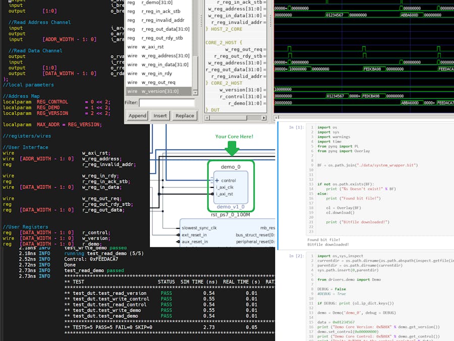
make waveThis will launch the waveform viewer, it will look something like this
The panel called 'signals' already has some signals inside. By default, this is not populated, instead, it is normally empty. The 'waveforms.gtkw' configures the signals to look like this. It's a great getting started point. A quick note: if you ever wanted to reload your signals (say you fixed something and wanted to see the results) you can always use the following command to reload the waveforms.
CTRL + SHIFT + RYou can open and close curly braces by double-clicking on them. As an interesting aside you can double click on the 'AXI signals' curly brace to see how much the axi_lite_slave.v core simplifies the signals.
We shouldn't need to worry about any of those signals. For that matter, we shouldn't need to worry about the 'HOST_2_CORE' or 'CORE_2_HOST' we should only worry about the 'r_control' and 'r_demo' signals.
The 'test_id' at the top associate the test run within 'test_dut.py' with the waveforms.
- test 0: read the version register
- test 1: write 0x01234567 to the 'r_control' register
- test 2: read 0xFEDCBA98 from the 'r_control' register
- test 3: write 0xABBA600D to the 'r_demo' register
- test 4: read 0xFEEDACA7 from the 'r_demo' register
Similar to the last part we can generate the IP core by moving to the base core directory:
cd <ip-cores repository>/cores/demo_part2Sourcing the Xilinx tools (if you haven't already)
source <Xilinx Base Dir>/Xilinx/Vivado/2019.2/settings64.shRunning the IP build script:
make xilinx_ip_no_guiNow if we open up the Vivado project where we built the image for Pynq project we built in the previous part. We can refresh the IP repository to access the new 'demo_part2'.
demo_part2 is now available
Replace the demo core by attaching the clock and reset signals and then deleting the AXI bus connection and connecting it to the demo_part2_0 core.
Every time you run the 'make xilinx_ip_no_gui' script you will probably see a notification on the top of your Vivado Pynq project notifying you that the IP has been updated, you can just run the 'Refresh IP Catalog'
The 'demo_part2_0' will automatically be selected, you should be able to upgrade it by pressing the 'Upgrade Selected'
Select 'Skip' when the next dialog comes up
We skip this because this will build the demo_part2 IP core individually, which is nice if weren't frequently changing it.
Run 'validate design'
If you see this:
We're ready to generate the bitstream, if not we may need to verify that our core has not automatically been mapped to our address bus, click on the 'Address Editor' tab on the top, and if you don't see this:
You will probably see this and just need to press on the auto-assign button
Re-run 'Validate Design' again and it should return 'Validation Successful'
Run 'Generate Bitstream'
After this is finished we should be able to move on to the Pynq board
On the Pynq boardVery similar to what we did in the previous part I'm going to go through the commands with less explanation.
Go to your Jupyter notebook web, specifically to the 'Projects/demo_part2/data' folder. upload the generated 'bit' and 'hwh' files that we just generated.
The files can be found in the following locations:
<vivado project base>/<project name>.runs/impl_1/system_wrapper.bitand
<vivado project base>/<project name>.srcs/sources_1/bd/system/hw_handoff/system.hwhRemember to change the 'system.hwh' to 'system_wrapper.hwh'
Similar to how the demo_part2_driver.py was modified to accommodate the new 'demo' register in the core the 'demo_part2.py' driver within Jupyter notebook found in the 'drivers' directory on the Pynq board was modified as well.
from pynq import PL
from .emmio import EMMIO


import sys
import os
import time

from array import array as Array

REG_CONTROL             = 0  << 2
REG_VERSION             = 1  << 2

class Demo (object):
    def __init__(self, name, debug = False):
        if name not in PL.ip_dict:
            print ("No such %s" % name)

        base_addr   = PL.ip_dict[name]["phys_addr"]
        addr_length = PL.ip_dict[name]["addr_range"]
        self.debug = debug
        if debug: print("Base Addr:           0x%08X" % base_addr)
        if debug: print("Address Length:      0x%08X" % addr_length)
        self.mmio = EMMIO(base_addr, addr_length, debug)

    def __del__(self):
        pass

    def get_version(self):
        data = self.mmio.read(REG_VERSION)
        return data

    # Set an entire Register
    def set_control(self, data):
        self.mmio.write(REG_CONTROL, data)

    # Get Entire Register
    def get_control(self):
        data = self.mmio.read(REG_CONTROL)
        return data
We added the 'REG_DEMO' variable and two functions that echo the set/get behavior for the control register.
from pynq import PL
from .emmio import EMMIO


import sys
import os
import time

from array import array as Array

REG_CONTROL             = 0  << 2
REG_DEMO                = 1  << 2
REG_VERSION             = 2  << 2

class Demo (object):
    def __init__(self, name, debug = False):
        if name not in PL.ip_dict:
            print ("No such %s" % name)

        base_addr   = PL.ip_dict[name]["phys_addr"]
        addr_length = PL.ip_dict[name]["addr_range"]
        self.debug = debug
        if debug: print("Base Addr:           0x%08X" % base_addr)
        if debug: print("Address Length:      0x%08X" % addr_length)
        self.mmio = EMMIO(base_addr, addr_length, debug)

    def __del__(self):
        pass

    def get_version(self):
        data = self.mmio.read(REG_VERSION)
        return data

    # Set an entire Register
    def set_control(self, data):
        self.mmio.write(REG_CONTROL, data)

    # Get Entire Register
    def get_control(self):
        data = self.mmio.read(REG_CONTROL)
        return data

    # Set an entire Register
    def set_demo(self, data):
        self.mmio.write(REG_DEMO, data)

    # Get Entire Register
    def get_demo(self):
        data = self.mmio.read(REG_DEMO)
        return data
Change the Jupyter Notebook to read/writethe demo register
A new cell was added that reads the current state of the demo register, then sets the register, and finally reads back the register, verifying the demo register is changed.
WRITE_DATA = 0xABBA600D
READ_DATA = None
print ("Read the current content of the Demo Register")
READ_DATA = demo.get_demo()
print ("Current Content of the DEMO register: 0x%08X" % READ_DATA)
print ("Write 0x%08X to the demo register" % WRITE_DATA)
demo.set_demo(WRITE_DATA)
print ("Read back the content of the demo register and verify that it maches with the WRITE_DATA")
READ_DATA = demo.get_demo()
print ("Read data: 0x%08X" % READ_DATA)
if READ_DATA != WRITE_DATA:
    print ("ERROR")
else:
    print ("READ_DATA matches with WRITE_DATA")
Run the entire notebook
We can now run all of the cells in the notebook where the last cell will look like this:
I've tried to break up this project into something more digestible but it did feel like drinking from a fire hose. This part demonstrated Cocotb and how it is a powerful simulator that can be used to demonstrate a core. We explored and modified the core. Updated the driver and the unit test, visualized the simulated results with GTKWave, and finally generated an AXI compatible IP. We then incorporated it into our Pynq project. We interfaced with our new core using Jupyter notebook. In the next part, we'll jump into the Vivado IP core generator. Up until now, we have been using a script to build the IP core, which works fine but if we want to adjust things we will need to use the GUI.
Appendix A: Add a new core to the MakefileIf you want to add a new core to your Makefile you will need to add it to your VERILOG_SOURCES here is an excerpt of the default demo core Makefile (with line numbers).
26 #DUT
27 VERILOG_SOURCES = $(TOPDIR)/hdl/axi_lite_slave.v
28 VERILOG_SOURCES += $(TOPDIR)/hdl/demo.v
Now we add a module called 'my_module.v'
26 #DUT
27 VERILOG_SOURCES = $(TOPDIR)/hdl/axi_lite_slave.v
28 VERILOG_SOURCES += $(TOPDIR)/hdl/my_module.v
29 VERILOG_SOURCES += $(TOPDIR)/hdl/demo.v
The Makefile will now include it in the build.
Appendix B: How the AXI Lite Slave Core WorksThe AXI Lite Slave core performs a lot of the low-level AXI Lite communication The details of which are described below:
Host sending data to core
- w_reg_rdy goes high when the host initiates sending data to the core (A marker in the picture below)
- The core decodes the address the host is sending to using w_reg_address
- The core reads the data from w_reg_in_data.
- The core acknowledges the transaction by setting the w_reg_in_ack high (B marker in the picture below)
Host reading data from core
- w_reg_out_req goes high when the host is requesting data from the core (A marker in the picture below)
- The core decodes the address the host is requesting data from using w_reg_address.
- The core writes the appropriate data to reg_out_data.
- The core sets r_reg_out_rdy high to indicate the data is ready to send (B marker in the picture below)
Initially, when I wrote this step I created a brand new core that made a pretty light show using an RGB LED. It had programmable state machines, smooth transitions, etc... but after I started writing out the steps I realized that would have made this simple project into a novel. If you are interested in playing around with the 'lightshow' core it is available in the 'cores' directory. To use it you will just need to run the 'xilinx_ip_no_gui' script and then attach one of the board's RGB LEDs to the appropriate GPIOs. That core demonstrates everything here along with how to read and write individual bits in registers. Adding new sub-modules, etc...


Comments
Please log in or sign up to comment.