


Hardware components | ||||||
 |
| × | 1 | |||
Software apps and online services | ||||||
| ||||||
| ||||||
- Part 1: Straight to the Finish Line
- Part 2: Customize our Core
- Part 3: Creating an IP Core Manually
- Part 4: Raw AXI Streams (you are here)
- Part 5: AXI Video Streams
In the previous part, we built an IP core manually. That core had a single AXI Lite interface. AXI Lite is great for configuring a core but is not designed to transfer a large amount of data quickly so in this part we are going to add two AXI Stream interfaces.
AXI Streams are useful for transporting data into and out of the core. I mostly use them for reading and writing video frames. In this part we are going to start with a simple AXI Stream demo that simply reads in raw data, inserts it into an internal FIFO, and writes the data out over another AXI Stream.
We will use what we learned in part 2 to simulate this core and then what we learned in part 3 to build an IP core. There is a lot to cover in this section so instead of walking through the whole coding process I'll provide the core and we can discuss it as we work through this.
At a high level- Review demo stream core
- Simulate the core
- Waveforms
- Build an IP core
- Create a Vivado Project
- Demonstrate on Pynq
- Conclusion
Move into the 'demo_axi_streams' core
cd <ip-cores>/cores/demos_axi_streamsIn the 'hdl' directory there are more files
axi_defines.v axi_lite_slave.v axis_2_fifo_adapter.v demo_axi_streams.v fifo_2_axis_adapter.v fifo.v- The 'demo_axi_streams.v', 'axi_defines.v' and 'axi_lite_slave.v' files are what you expect.
- fifo.v: A simple FIFO is used to store the data from the incoming AXI Stream and output it to the output AXI Stream.
- axis_2_fifo_adapter.v and fifo_2_axis_adapter.v are both converters that convert between AXI Stream and a FIFO and vice versa. The files are very small, essentially just attaching signals. These probably could be removed and all of this done within the 'demo_axi_streams.v'.
The major difference between the 'demo.v' of the previous part and 'demo_axi_streams.v' is the addition of:
- Parameters to define the AXI Stream
- AXI Stream Ports
- Submodule Declaration
Parameters to configure the AXI Streams
The parameters of the AXI Stream are similar to the AXI Lite, the Stream width can be adjusted although it must be a power of 2 (8, 16, 32... 1024). The FIFO depth is the FIFO inside of the core that will temporarily hold the data before sending it.
...
module demo_axi_streams #(
  parameter ADDR_WIDTH          = 16,
  parameter DATA_WIDTH          = 32,


  parameter AXIS_DATA_WIDTH     = 32,
  parameter AXIS_KEEP_WIDTH     = (AXIS_DATA_WIDTH / 8),
  parameter AXIS_DATA_USER_WIDTH= 0,
  parameter FIFO_DATA_WIDTH     = AXIS_DATA_WIDTH + 1 + 1,
//XXX Must be a power of 2
  parameter FIFO_DEPTH          = 4,
  //parameter FIFO_DEPTH          = 8,
  //parameter FIFO_DEPTH          = 16,
  parameter INVERT_AXI_RESET    = 1,
  parameter INVERT_AXIS_RESET   = 1
)(
...
AXI Stream Ports
There is a new clock and reset ports specifically for AXI Streams, in the demo project we make for this it will be the same clock as the AXI Lite interface but the two different buses can run at different frequencies.
The input and output AXI Streams both have 'data', 'ready' and 'valid' as you would expect but they also have 'user' and 'last'. These two other signals will not be used in this design but are very useful when you want to send video or audio data. We'll go into a more detailed explanation below when we attach the signals to an interface.
...
  //AXI Stream
  input  wire                             i_axis_clk,
  input  wire                             i_axis_rst,

  //Input AXI Stream
  input  wire                             i_axis_in_tuser,
  input  wire                             i_axis_in_tvalid,
  output wire                             o_axis_in_tready,
  input  wire                             i_axis_in_tlast,
  input  wire   [AXIS_DATA_WIDTH - 1:0]   i_axis_in_tdata,

  //Output AXI Stream
  output wire                             o_axis_out_tuser,
  output wire                             o_axis_out_tvalid,
  input  wire                             i_axis_out_tready,
  output wire                             o_axis_out_tlast,
  output wire    [AXIS_DATA_WIDTH - 1:0]  o_axis_out_tdata
);
...
Submodule Declaration
For this example project, we attach the AXI Stream signals to a FIFO. For this version, we use these adapter modules (axis_2_fifo_adapter and fifo_2_axis_adapter) to convert the AXI Stream signals to the FIFO. The modules are both very small but if you would like to use a FIFO in another project it is relatively easy to import these modules and glue them together like the following.
//Convert the Incoming AXI Stream Signals to FIFO Signals
axis_2_fifo_adapter #(
  .AXIS_DATA_WIDTH    (AXIS_DATA_WIDTH      )
)a2fa(
  .i_axis_tuser       (i_axis_in_tuser      ),
  .i_axis_tvalid      (i_axis_in_tvalid     ),
  .o_axis_tready      (o_axis_in_tready     ),
  .i_axis_tlast       (i_axis_in_tlast      ),
  .i_axis_tdata       (i_axis_in_tdata      ),

  .o_fifo_data        (w_fifo_w_data        ),
  .o_fifo_w_stb       (w_fifo_w_stb         ),
  .i_fifo_not_full    (w_fifo_not_full      )
);

fifo #(
  .DEPTH              (FIFO_DEPTH           ),
  .WIDTH              (FIFO_DATA_WIDTH      )
) axis_fifo (
  .clk                (i_axis_clk           ),
  .rst                (w_axis_rst           ),

  .i_fifo_w_stb       (w_fifo_w_stb         ),
  .i_fifo_w_data      (w_fifo_w_data        ),
  .o_fifo_full        (w_fifo_full          ),
  .o_fifo_not_full    (w_fifo_not_full      ),


  .i_fifo_r_stb       (w_fifo_r_stb         ),
  .o_fifo_r_data      (w_fifo_r_data        ),
  .o_fifo_empty       (w_fifo_empty         ),
  .o_fifo_not_empty   (w_fifo_not_empty     )
);

//Convert The FIFO Signals to AXI Stream Signals
fifo_2_axis_adapter #(
  .AXIS_DATA_WIDTH    (AXIS_DATA_WIDTH      )
)f2aa(
  .o_fifo_r_stb       (w_fifo_r_stb         ),
  .i_fifo_data        (w_fifo_r_data        ),
  .i_fifo_not_empty   (w_fifo_not_empty     ),

  .o_axis_tuser       (o_axis_out_tuser     ),
  .o_axis_tdata       (o_axis_out_tdata     ),
  .o_axis_tvalid      (o_axis_out_tvalid    ),
  .i_axis_tready      (i_axis_out_tready    ),
  .o_axis_tlast       (o_axis_out_tlast     )
);
There are some register/wire declarations to support these changes but besides that nothing else has changed. We didn't do anything with the AXI Stream data but this is enough to verify the functionality of the AXI Streams.
Simulate the coreMove into the 'tests' directory
cd testsrun 'make'
makeThere are more tests to run through the foreseeable AXI Stream permutations, here is an excerpt from the test results:
test_dut.test_read_version                                            PASS
test_dut.test_write_control                                           PASS
test_dut.test_read_control                                            PASS
test_dut.test_axis_write                                              PASS
test_dut.test_axis_write_and_read                                     PASS
test_dut.test_axis_write_and_read_with_source_idle                    PASS
test_dut.test_axis_write_and_read_with_sink_back_preassure            PASS
test_dut.test_axis_write_and_read_with_sink_idle_and_back_preassure   PASS
Notice that all the initial 'demo_part1.v' tests are still there. There is no need to disable those tests and they help confirm that we didn't break any of our old features when adding new ones.
We added five more tests, these test out various conditions for the AXI Stream.
Side note about Interfacing with AXI
Cocotb is a python based co-simulation testing framework and doesn't natively provide support for interfacing with an AXI bus. cocotbext-axi is a very helpful repository that is used to interface with all the AXI bus signals within Cocotb. Previously, I had either used the AXI interfaces provided by cocotb-bus or written my own but once I saw how many features this repository offered I found that Alex Forencich did a much better job, so huge thanks to him.
WaveformsOriginally I went through the relevant waveforms but it does slow the post down. If interested, go to Appendix A to view the waveforms of the AXI Stream-related tests.
Build an IP coreIn the last part, we went through the process of building an IP core manually so instead of going through it again we can run the script that will generate the IP core, open up the Vivado IP project, and go through it instead. Navigate to the base 'demo_axi_streams' directory:
cd <ip-cores>/cores/demos_axi_streamsSource the Xilinx tools
source <Xilinx Base Dir>/Xilinx/Vivado/2019.2/settings64.shRun the script
make xilinx_ipThis should configure the project in a similar way to what we did in part 3 with the addition of also creating the interfaces for the AXI Streams.
Input AXI Stream
The generated Vivado project is ready for us to just create the IP but if we go to the 'Ports and Interfaces' section we can click on 'axis_in' to get the AXI Stream configuration.
The following is the AXI Stream input configuration. The Interface Definition is 'axis_rtl' and the Mode is 'slave'.
Clicking on the Port Mapping tab we can see how the ports are mapped. Notice that there are two extra signals that I mentioned above. These are the 'TUSER' and 'TLAST' settings. These signals are not needed for raw data streams but are useful for video and audio data. The 'TUSER' is used to indicate that a new frame is sent and the 'TLAST' is asserted at the end of every line of video data. This helps a lot with keeping video frames aligned.
The same can be shown for the AXI Stream output interface. Selecting the AXI Stream output:
You will then see the following configuration.
Note that the Interface Definition is the same, it's just the mode is different.
Similar to the input side the 'TLAST' and 'TUSER' are both mapped.
Associate Clocks
After looking at the streams you can right-click on each of the interfaces and make sure their 'associated clocks' correctly point to 'i_axis_clk'
Also, see that the 'i_axis_rst' is correctly associated with 'i_axis_clk' as well.
Move on to 'Review and Package' and click 'Package IP'
You should see this:
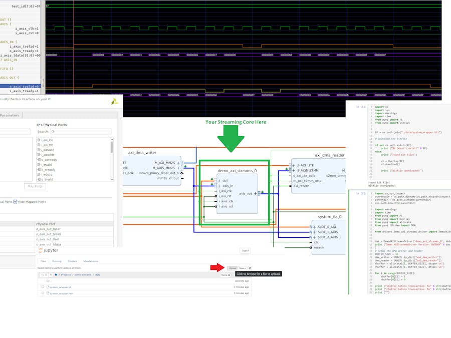
Now we need to incorporate it into a Vivado Project. To simplify this process I've attached a zip file called: AXI Stream Demo Project, unzip the project, and open it. This project already has a 'demo_axi_streams'. You should see something like this
To help us a bit we can adjust the view by using that drop-down box at the top
This changes the color to highlight buses. The normal AXI bus is green, AXI Lite is orange and AXI Streams are blue. Zooming into our new core. Your view might have a different color scheme.
I've also shown the two cores surrounding our core, they are AXI Stream DMA controllers. The 'axi_dma_writer' gets data from external memory and writes it, in stream form, to our core. The 'axi_dma_reader' receives data from the core and writes it to the external memory.
We also have a logic analyzer attached to the AXI Lite bus for the core, the incoming stream, and the outgoing stream. We can verify that our core is behaving as it does within the simulation.
This project has a cached version of our demo_axi_stream core, to use the core that we created, we will need to update the IP core repository. In the flow navigator. Select 'Settings' then select 'IP->Repository' In the window press '-' to remove the current repository then press '+' to add the location of your 'ip-cores' repository. The tool will scan the repo and then we'll have access to our new core.
You should see a yellow bar across the top of the screen with the option to 'Report IP Status', click on it.
On the bottom, you will see an 'IP Status' area and you should see 'demo_axi_streams_0' with a Recommendation of 'Upgrade IP', click on that.
You should get a small notification that the update was complete, you can press 'skip' on the next dialog block asking you to build this individually.
NOTE: If you don't get the yellow bar on the top or see this area you may need to remove the 'demo_axi_streams_0' and pull in a new one from the IP Catalog, use the above images to see how it is connected.
Generate a bitstream
Click on Generate Bitstream
Similar to what we did previously, we need to upload the 'bit' and 'hwh' files. Within Jupyter notebook so move to
Projects/demo-streams/dataPress the 'upload' button and find the 'system_wrapper.bit' and 'system.hwh' files
The files can be found in the following locations:
<vivado project base>/<project name>.runs/impl_1/system_wrapper.bitand
<vivado project base>/<project name>.srcs/sources_1/bd/system/hw_handoff/system.hwhRemember to change the 'system.hwh' to 'system_wrapper.hwh'
Now you can open up the demo_streams python notebook and run all the cells
The picture above is unreadable so here is a link to the notebook on Github. The relevant points are setting up the DMA to write and read data. From the output, you can see that both the sbuffer (send buffer) and rbuffer (receive buffer) are initialized. The send buffer is initialized with an incrementing number pattern while the receive buffer is cleared. After both are set up the transaction starts and the data is read back from the rbuffer. The rbuffer after the transaction matches up with the send buffer before the transaction showing the data has passed through.
ConclusionThis project showed how to implement AXI streams to send/receive raw data to and from the core. Sending raw data can be used for the following:
- Time of flight data in distance sensing.
- IQ data in Software Defined Radio applications.
- Telemetry data when using IMUs.
In the next and final installment of this multi-part project, we'll go over sending video data out.
Appendix A: WaveformsThe first four waveforms are not very interesting while 5, 6, and 7 show the AXIS streams in various configurations.
Test 4: axis_write_and_read: A test of the input and output streams with no back pressure:
The thing to note is the yellow and orange traces. The orange is the 'valid' signal and the 'yellow' is the ready signal, They are constantly high with a single clock cycle delay of the data as it propagates through the FIFO.
Test 5: axis_write_and_read_source_idle: A test of the input and output streams with the source stalling every once in a while.
Here the orange trace (valid) goes low whenever the source is stalled, This artificial stalling is controlled in the test bench.
Test 6: axis_write_and_read_with_sink_back_pressure: A test of the input and output streams with the sink applying backpressure.
The orange line (valid) is high the entire time indicating that the source is always ready while the yellow (ready) signal goes low indicating the sink is not ready, at one time the sink even propagates as backpressure into the source through the FIFO.
Test 7: axis_write_and_read_with_sink_idle_and_back_preassure: Both the source idles and the sink applies back pressure.
The source and sink both, at times, idle and apply back pressure to demonstrate the system's ability to handle starts and stops on both sides.


Comments
Please log in or sign up to comment.