In this tutorial I want to show you how to build several most common sensors and actuators for a home automation system.
Also the integration into a MQTT broker covered in this tutorial. The integration into a broker makes it possible to use the sensors and actuators in home automation systems like Wirehome.Core later on.
To avoid listing of all required resistors and parts (and their respective shop links) I decided to use the Super Starter Kit UNO R3 Project from ELEGOO for this tutorial. It contains mostly everything which is required to build the sensors and actuators. Also most of them are perfect for home automation purposes.
No soldering is required because the starter kit also contains a breadboard, jumper wires, shields, motors with already soldered cables, all required kinds of resistors etc. This makes it easy even for starters which have no experience with soldering etc.
ELEGOO send the starter kit to me for free (sponsoring). If you already own the used sensors and parts in this tutorial you can still use them as well. The ELEGOO UNO is compatible with the original Arduino UNO and even an Arduino NANO because the used microcontroller in all of them is an ATMEGA328.
The following picture shows all parts which are included in the starter kit.
Not all of these parts are used in this tutorial but most of them are perfect for home automation projects like the following ones.
- Button
- Temperature & Humidity Sensor
- IR Remote
- LED (lamp)
- Motor (ventilation)
- Buzzer (doorbell)
- LCD Module
Unfortunately the starter kit contains no device for connecting with a LAN via cable or WiFi. So an additional LAN board like the mini ENC28J60 Ethernet LAN Network Module is required.
Connecting with the LANIn order to integrate the sensors and actuators into the LAN the first step is to prepare the LAN board and its connection with the UNO board. Only 6 wires must be added to the UNO including power supply. The connections are as follows.
// LAN    UNO
// ----------
// CS  >  D10
// SI  >  D11
// SO  >  D12
// SCK >  D13
// VCC >  3.3V (important! do not use 5V!)
// GND >  GND
The following picture shows the board with all wires hooked up.
I personally prefer the IDE PlatformIO in combination with Visual Studio Code from Microsoft.
The installation and preparation is not covered in this tutorial because there are way better tutorials available. I recommend to use the following one: https://docs.platformio.org/en/latest/ide/vscode.html#installation
After downloading the code from the repository which is attached in this tutorial you should open the folder in VS Code.
Preparing the MQTT environmentAll sensors and actuators will connect to a shared broker. This broker uses the MQTT protocol and is responsible for receiving sensor values and sending actuator commands.
Several open source MQTT brokers are available for use like mosquitto (https://mosquitto.org/download/). There are also public ones like the one from HiveMQ (http://www.mqtt-dashboard.com/).
You can also build your own broker in C# using the open source library MQTTnet with a few lines of code (https://github.com/chkr1011/MQTTnet).
For this tutorial the broker mosquitto will be used. Installing and configuring the broker may depend on your OS and is described here: http://www.steves-internet-guide.com/install-mosquitto-broker/
I use mosquitto running on Ubuntu 10.04 which runs in the Linux Subsystem of Windows 10.
For testing purposes the MQTT client MQTTBox (http://workswithweb.com/mqttbox.html) is used to monitor message traffic and publishing messages.
MQTT basicsMQTT is used as the preferred and only way of communication with sensors and actuators in this project. The protocol supports lots of useful features but the key point of the protocol is: It allows sending and receiving of messages which contain a topic and a payload.
The topic is the identifier of the data. It behaves like a key and the payload is the actual data. The following table shows some examples.
// Topic                         Payload
// -------------------------------------
// awesome_device/temperature    21
// awesome_device/lamp           off
// awesome_device/button         pressed
Another important part of MQTT is that every device has its own ID (called the ClientID) which must be unique for every device. For this project the device is called "awesome_device".
For more information about the features of MQTT in general please visit: https://www.hivemq.com/docs/4/hivemq/introduction.html
Shared codeApart from code which is accessing the hardware like a button or LED some shared code is required for all devices. It is responsible for the following things.
- Enable logging via Serial port
- Enabled LAN module
- Connect with MQTT broker and maintain the connection
This code is only covered in this chapter but required for all devices. The shared code is located in the file shared.cpp.
First startBefore building the devices and connecting them with the broker it should be tested that all components are up and running. The following checklist shows all steps to perform.
- Change the broker IP address (_brokerIP) in shared.cpp
- Start the broker using mosquitto -v
- Ensure that the port 1883 is not blocked on the PC which runs the broker
After connecting the board with power via USB and LAN the upload of the firmware should be started via clicking the uplaod button at the bottom in VS Code. The port of the UNO etc. should be detected automatically. If this works the Serial Monitor should be opened to see debug messages from the UNO. If they do not appear it might be required to press the reset button at the UNO. If everything is configured properly the output should look like the one on the following picture.
Also the connection of MQTTBox must be created. Basically it is only required to set the broker address. The following screenshot shows the proper settings.
The device is already prepared to reply with a PONG for every PING message. This can be tested via sending a message using MQTTBox which has the topic "awesome_device/PING". The device will publish a message with the topic "awesome_device/PONG". But before this is shown in MQTTBox it is required to subscribe to the required message because by default not all messages are distributed to all devices. So subscribing to "awesome_device/#" is required.
The following screenshot shows how to property subscribe and publish.
After subscribing and publishing the PING message the device should respond and the respective message should be shown in MQTTBox like in the following screenshot.
If this works you can go ahead with the next steps to build the home automation devices. If something went wrong please start at the beginning and make sure every step works and all connections are correct etc. If you need support please write to the comments below.
Building the devicesAll samples are described without an attached LAN board to keep them small and simple. But the LAN board is mandatory for every device.
Also the used Pins for sensors etc. are different so that multiple devices can be added to the breadboard at the same time without changing the code.
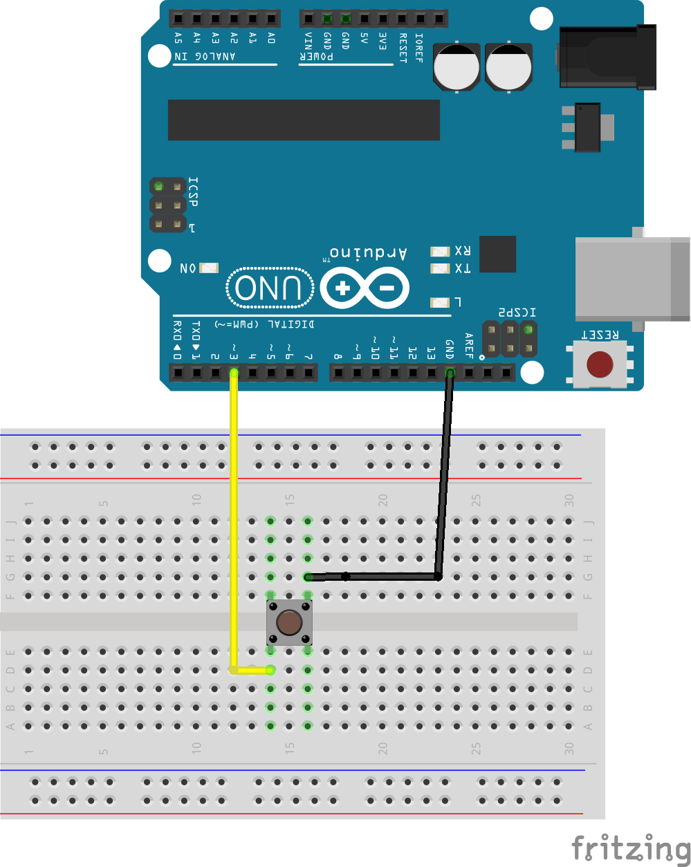
Building a buttonOne of the most simple kinds of sensors are buttons. The state of a button is either pressed or released. There is nothing in between.
The following picture shows the wiring.
Often a pull-up resistor (10k) is needed between the GPIO and 5V but the internal pull-ups of the UNO are working fine for this tutorial. If a button press is registered without any interaction it may be added. Several of them are part of the starter kit.
The button will send MQTT messages whenever the state has changed. Holding the button down for a certain time has no impact on message generation. The following table shows all kinds of MQTT messages which are generated.
// Topic                    Payload
// ---------------------------------
// awesome_device/button    pressed
// awesome_device/button    released
To enable the button functionality in the sample code it is required to comment in the setup and loop code for that device type. The final code should look like the following snipped.
void setup()
{
  // Shared code
  setupShared();

  // Device code
  setupButton();
}
void loop()
{
  loopShared();
  loopButton();
}
When starting the UNO with the code above it will send a MQTT message whenever the button is pressed or released. For more details how the state is read and the MQTT message generated please have a look at the file src\button.cpp. This file contains the device specific code for a button and some comments describing it.
The button related messages should be visible in MQTTBox like shown in the following picture.
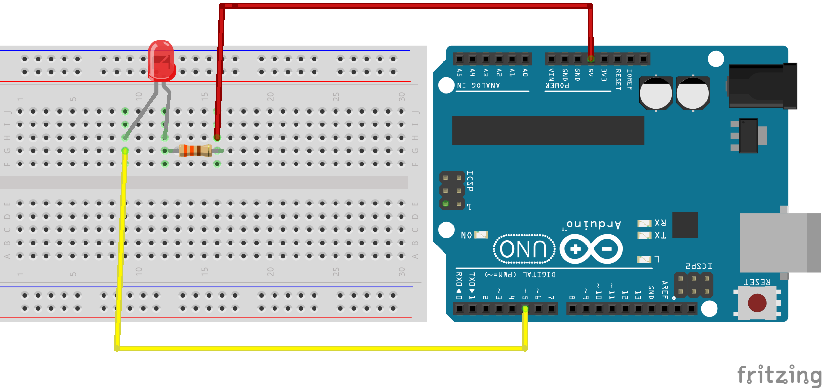
One of the most simple kinds of actuators are lamps. They either have the state on or off. Some lamps may also have a brightness or color value but all of them are either on or off.
The following picture shows the wiring.
The difference in comparison to a button is that the device will react to a certain MQTT message. This requires a payload to specify purpose (topic) and parameters (payload). The MQTT messages used for the interaction with the lamp are shown in the following table.
// Topic                  Payload
// ------------------------------
// awesome_device/lamp    on
// awesome_device/lamp    off
The topic remains the same but the payload is different according to the target state.
To enable the lamp functionality in the sample code it should be modified to look like the following snipped.
void setup()
{
  // Shared code
  setupShared();
  // Device code
  setupLamp();
}
void loop()
{
  loopShared();
  loopLamp();
}
If you want to see how the lamp is actually triggered by an MQTT message please have a look at the file src\lamp.cpp. This file also has some comments which are explaining how the interaction with the LED works in detail.
To turn a lamp on the proper MQTT message must be published using MQTTBox. The following picture shows such a message.
If everything is properly configured the lamp should turn on and off depending on the received MQTT messages. If you experience problems please check the following list.
- Is the source code prepared as described?
- Is the firmware uploaded?
- Are the received MQTT messages are shown in the Serial Monitor?
- Is the polarity of the LED correct?
- Is the correct GPIO used?
- Is the device connected with the MQTT broker?
Exercises
If you want to try something on your own you can try to combine the button and the lamp example. Both have different GPIOs so that both can be added and run at the same time. There are predefined methods available to interact with the lamp. You can try to toggle the state of the lamp by pressing the button or processing MQTT messages. The methods for this are turnLampOff,turnLampOff, and isLampOn. If you need assistance please write to the comments below.
The next step is adding brightness support for the lamp. There is a comment in the source code which gives some hints. You can try to add another topic or convert the existing one to accept the brightness value (0-255).
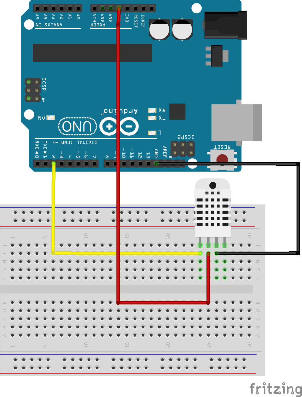
Building a temperature and humidity sensorAfter creating some interactive sensors and actuators this sample will cover an autonomous sensor which reports the current temperature and humidity every 5 seconds automatically. The starter kit contains a DHT11 which is used for this measurement.
The following picture shows the wiring.
The sensor will publish two different MQTT messages every 5 seconds. The values are not merged together in the payload to keep the messages clean (only 1 key with 1 value) and make parsing easy. The following table shows these MQTT messages.
// Topic                         Payload    Unit
// ------------------------------------------------
// awesome_device/temperature    22.5       °C
// awesome_device/humidity       84         %
To enable the DHT sensor functionality in the sample code it should be modified to look like the following snipped.
void setup()
{
  // Shared code
  setupShared();
  // Device code
  setupDht();
}
void loop()
{
  uint64_t elapsedMillis = loopShared();
  loopDht(elapsedMillis);
}
If you want to see how the sensor actually accessed please have a look at the file src\dht.cpp. This file also has some comments which are explaining how the 5 seconds delay works.
If everything is configured properly you should see the temperature and sensor humidity in MQTTBox like in the following picture.
Exercises
If you want to improve this sample you can try to re organize the topics so that the device will not receive the messages it also sends. Some dedicated topics for input and output data may be the solution.
Another improvement may be connecting the sensor with the lamp and turning it on as soon as a certain threshold is reached.
At least you can try to avoid sending the sensor values all the time and only perform this operation if a certain topic was received.
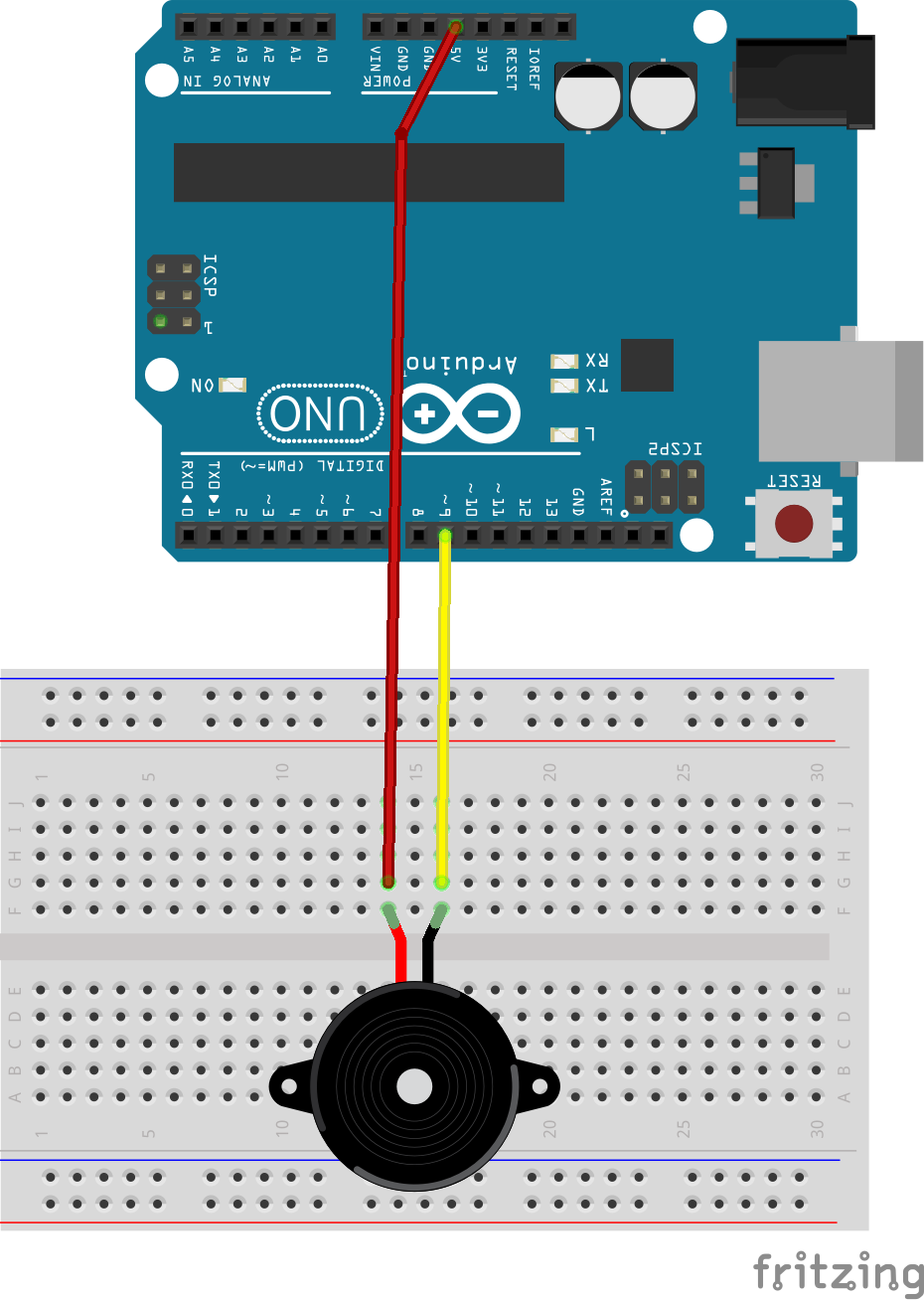
Building a doorbellThe starter kit also contains two different kinds of buzzers. They are perfect for building a doorbell. For this device the passive buzzer is used. This kind of buzzer is not able to play different sounds. I just plays the same sound at the same volume whenever it gets power.
The following picture shows the wiring.
Basically the doorbell works in the same way as the lamp but instead of sending a state, this time only a trigger is being sent. The device will take care of enabling the buzzer and disabling it after 1 second. Without this logic the sender must ensure that the buzzer gets deactivated after some time. If this fails for some reason the doorbell will ring forever.
The following table shows how the trigger is defines.
// Topic                              Payload
// ------------------------------------------
// awesome_device/doorbell/trigger
To enable the doorbell functionality in the sample code it should be modified to look like the following snipped.
void setup()
{
  // Shared code
  setupShared();
  // Device code
  setupDoorbell();
}
void loop()
{
  uint64_t elapsedMillis = loopShared();
  loopDoorbell(elapsedMillis);
}
If you want to see how the doorbell works in detail please have a look at the file src\doorbell.cpp. This file also has some comments which are explaining how the auto turn off works.
Troubleshooting
- If nothing happens but the MQTT messages are shown in the Serial Monitor please make sure that you are using the correct kind of buzzer. The starter kit contains two of them.
Exercises
The default version of the doorbell only plays a sound for one second. You can try to add the required duration to the payload. This allows playing different sounds for different situations.
The trigger restarts the timeout every time which leads to a continuous beep sound when trigger are being sent rapidly. Try to extend the code to avoid this.
Building a remote control receiverAnother kind of button is a remote control. It behaves similar as the button but a single remote control contains a lot of buttons. The starter kit contains a remote control with 21 unique buttons. The transport layer is an infrared signal which is read via the IR Receiver Module from the starter kit.
The following picture shows the wiring.
Whenever a button is pressed the remote control will send a unique code which maps to a certain button. This value will be send in the payload within a MQTT message. The following table shows some of the available keys and their values.
// Topic                      Payload   Button
---------------------------------------------------
// awesome_device/ir/value    ffa25d    POWER (red)
// awesome_device/ir/value    ff629d    VOL+
// awesome_device/ir/value    ff6897    0
// awesome_device/ir/value    ff9867    EQ
// awesome_device/ir/value    ff52ad    9
When pressing the keys it might happen that the value ffffffff is being sent in the payload. This special value indicates that the previous button is still pressed. When this value is no longer sent the actual button was released.
To enable the remote control functionality in the in the sample code it should be modified to look like the following example.
void setup()
{
  // Shared code
  setupShared();
  // Device code
  setupIRRemote();
}
void loop()
{
  uint64_t elapsedMillis = loopShared();
  loopIRRemote();
}
If you want to see how the IR Receiver works in detail please have a look at the file src\irRemote.cpp.
Exercises
The default version of the example code only sends the received code. It is not converted to a proper button name like "VOL+" etc. You can try to add this mapping and send the proper button name instead of the numeric value of the code.
In comparison to the simple button there is no message for pressed and released published. You can try to to deal with the special value and try to build the same feature for a remote control button. For this case the state should be moved to the payload and the affected key should be part of the topic like "awesome_device/ir/VOL+".
Building a light (lux) sensorA photo cell is also part of the starter kit and can be used to measure the light intensity. This kind of sensor requires an analog GPIO to be used instead of a digital one. Analog GPIOs can read the current voltage and report it as a value between 0 (0 V) and 1023 (5 V).
There is a problem when it comes to measuring the light intensity using a photocell. The range of possible values is always 1024 (0 - 1023). This means that everything between dark (night) and bright (midday sun) must fit into this range. There are scenarios where you may want to differentiate 10 kinds of bright but there are only 5 steps left because the sensor supports the whole range from night to day. To get around this you need to play around with different resistor values. A value of 1 K will result in a quite full range from dark to bright. If you are only interested in values at day you can try a 10 K resistor which will cut off the darker parts so that more granular steps are available to differentiate the brightness.
The following pictures shows the wiring.
The value of the analog GPIO is read every second and published as the payload within a MQTT message. The following topic shows some examples.
// Topic                       Payload    Comment
----------------------------------------------------------------------------
// awesome_device/photocell      7        (dark room with active PC monitor)
// awesome_device/photocell    170        (dark room with a lamp)
// awesome_device/photocell    876        (light from smartphone)
To enable the light sensor functionality in the in the sample code it should be modified to look like the following example.
void setup()
{
  // Shared code
  setupShared();
  // Device code
  setupPhotocell();
}
void loop()
{
  uint64_t elapsedMillis = loopShared();
  loopPhotocell(elapsedMillis);
}
If you want to see how the light sensor works in detail please have a look at the file src\photocell.cpp.
General troubleshooting & Tipps- If not TCP connection could be made make sure you are connected to LAN and a proper IP address is printed to the Serial Monitor.
- If the MQTT connection gets lost you must restart the device. Reconnects are not implemented. You can also try to add reconnect functionality.
- The used GPIOs are different ones for nearly every device. This allows running multiple devices at once. You can try to combine them.
- The starter kit contains a 9V battery and a proper connector. You can use it to place the temperature sensor for example to another place (if your LAN cable is long enough).
- The prototype expansion board allows soldering of several sensors and having a portable and robust device.
All of the above built devices can be integrated into home automation systems like Wirehome.Core. It is also possible to write a broker in C# (using MQTTnet) which will also perform some business logic like turning on a lamp at device A when pressed message was received from device B. This will be covered in another article here on hackster.io.
Thank you for reading! If you like this tutorial please share it and respect it.
If you have some more ideas fordevices built with the starter kit please share them in the comments and create a proper pull request for the coderepository.





Comments
Please log in or sign up to comment.