


Hardware components | ||||||
 |
| × | 1 | |||
| × | 1 | ||||
 |
| × | 1 | |||
 |
| × | 1 | |||
Software apps and online services | ||||||
| ||||||
 |
| |||||
| ||||||
Hand tools and fabrication machines | ||||||
 |
| |||||
 |
| |||||
 |
| |||||
 |
| |||||
I've revived the old main board from the graveyard of hardware inventory. This board was used to be an MVP product for Startup company. Back then in 2 years ago, when Startup still in hype and there are plenty of investors who want to generously generated cash for the startup, we see this big opportunity in Industrial IOT area. I and the other founders are taking the first step to realize the idea to build this startup company that mainly focusing on Industrial IOT applications.
One thing that I notice from those manufacturing industries that they use standard industrial measurement tools, which is lead to one similarities that these tools using standard interface called MODBUS. From this opportunity, this hardware is born to bridging the MODBUS to Lorawan/wireless data.
In this project, the main target is to revive the hardware so it able to collect data from Modbus sensors, Save the data to SDCard or Internal data buffer, doing data conversion, and sending the data to the cloud.
Soil sensor with MODBUS protocol capability is being used in this project to do the PoC (Proof of Concept) since that was the only sensor that support modbus in my junk drawer.
Main DiagramFrom the diagram below, it explains roughly the idea that will be achieved in this project. From the bottom to the top, there is soil sensor with modbus RTU - RS485 interface able to collect the soil quality information. In order to get the data inside the sensor, the Main board need to perform modbus RTU data query with help of UART to RS485 board converter. With such of query command, we will able to collect the Temperature, volumetric water content (VWC), and Electrical conductivity (EC) of the soil.
Once the board get soil data, the main board will do conversion to the actual value and send the conversion to the lorawan gateway. To be able to send in lorawan protocol and lorawan radio, ESP32S3 will need RFM95 support to do such things. Between RFM95 and ESP32S3 are communicated through SPI interface where the physical connection are made internally on the board.
Lorawan gateway will receive the data from main board and store the data internally in lorawan local server. in this lorawan gateway, RAK Gateway module are being used as concentrator with Balena Fin Board as the Gateway base board. The base board it self are able to run RPi OS and Chirpstack as the lorawan server. From this stage, we are able to view the data that was sent by main board/ node.
Thingsboard is need as dashboard to give interactive view of sensors data. The Lorawan Gateway may need a bridge to perform data transfer to the Thingsboard. In Thingsboard free edition, this Chirpstack - Thingsboard integration is not supported, so manual bridging may need to be created between Chirpstack - Thingsboard.
Hardware listTo build up this project, several hardwares are required:
- Custom Modbus to Lorawan Board
- Lorawan Gateway
- UART/TTL to RS485
- Soil Measurement Sensor with Modbus-RTU Support
- Cloud server/ Thingsboard Server
Expicitly, to build up the Custom Modbus - Lorawan Board:
- ESP32S3
- RFM95W
- MPPT Solar Charger
- SD Card Data interface and Socket.
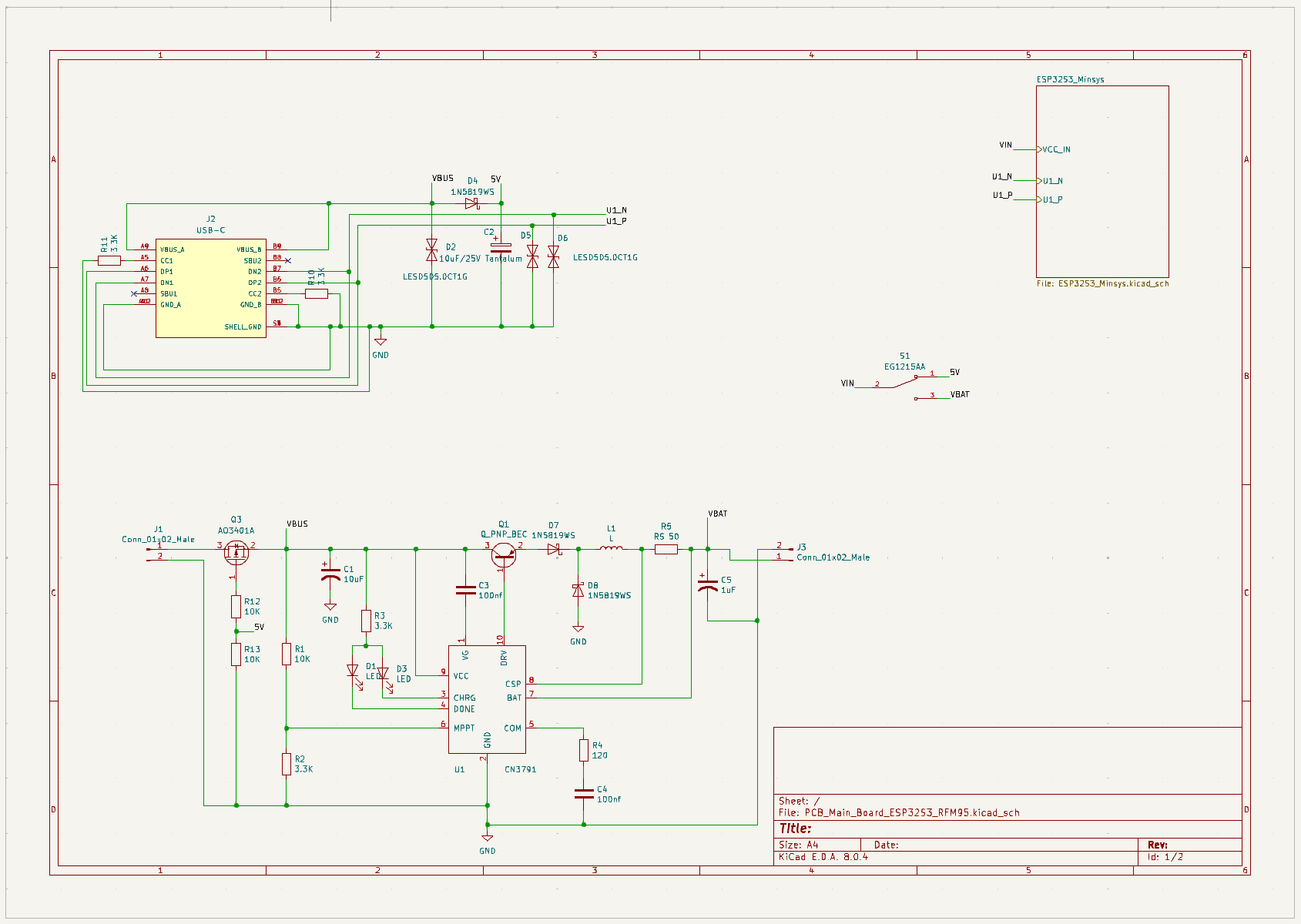
Connection diagram from Mainboard to the sensor is explained below. The Mainboard is powered through USB port and distributed to all module an components on the board. The Voltage conversion 3.3V also distributed to outer of board to supply board support, In this project is RS485 board converter.
Uart connection also been made through jumper wire to connect the TTL port of UART-RS485 to main board. At the other side of converter board, the pin A and B connected to sensor pins. In order to the sensor working normally, this project is using external 12V adaptor and connect the 12V output to the input power pins of the soil sensor.
To get better view on the Mainboard, this diagram explain in high level overview on the connection of each modules. The main controller of this board is ESP32S3 that capable to deliver performance in wireless connectivity such as WIFI and BLE, also it has some peripherals that can be used as communication interface.
As described from this diagram, ESP32S3 is connected through SPI connection and send the command/data to the support module (RFM95), also it perform read/write data file to SDcard through SPI interface. ESP32S3 also reserved others GPIO that can be used as other purposes.
Power delivery is delivered by Power Contoller that supplied the power to all of the modules on the board. There are 3 sources of power that can be switched in between, those are USB, Solar Panel and Battery.
Since this board has been long in hibernate, functional check might needed to ensure that the board behave normally. Some of the functional checks are:
- Lorawan connectivity test
- SD card data Wr/R test
- Modbus Query test
More detail on this checks are covered in the video/recordings.
Firmware Diagram and ImplementationThe main flow diagram to do the job properly is described in diagram below. After few trials, this diagram need to be updated by excluding the Write and Read command to SD Card due to library issue where the Espressif - Arduino VSPI is not working as expected, resulted in wrong behavior.
Started with initializing the peripherals, and starting the lorawan routine/event. This lorawan scheduling time is every 60 second, so lorawan gateway will receive the latest data every minutes. Once started, the lorawan firmware will taking care every event and scheduling automatically.
Modbus data query started once lorawan initialized. The board will send Modbus RTU command in modbus data format. For more detail about modbus RTU, we can follow this information.
From the modbus RTU code, based on the modbus data protocol
uint8_t modbus_cmd[]={0x01, 0x03, 0x00, 0x00, 0x00, 0x0A, 0xC5, 0xCD};modbus addr : 0x01
Function code : 0x03
Start addr : 0x0000
Length requested data : 0x000A
CDC : 0xC5CD
Once the modbus slave/target send the feedback, the firmware will do conversion from modbus value to its actual value, and copy the them into lorawan data payload.
Since there are multiple tests that need to be performed, it has been developed multiple firmware on this project. The main implementation is ESP32S3_RFM_Firmware that cover all of the process starting from acquiring soil sensor data to sending the data to cloud.
The code below is the program to run the main flow, this code is written based on the diagram firmware above. starting from peripheral init, read data modbus and sending data measurement. We might notice that how the modbus data query and lorawan event is co-exist. The lorawan stack/event need to be separated from modbus data query in other stack, this method will prevent overflow in the main stack due to lorawan event and priority.
From the code also performed data modbus conversion to its actual value and store them inside lorawan payload. The modbus query was ignited every 20 Sec but the data will be transmitted every 1 minutes, means the latest/ greatest data that will be received by platform and lorawan server.
/*

ESP32S3 MAIN Firmware
Author: dadanugm07@gmail.com
Date: 31-12-2024
REV:

*/

#include "lorawan_app.h"
#include "sd_app.h"
#include "modbus_app.h"


extern uint8_t lorawan_data[128];
extern uint8_t modbus_data[128];
float Temperature;
float VWC;
float EC;

static const char *TAG = "MAIN";
void ModbusTask(void *pvParameters);

void setup() {
    rfm_init(); // init Lorawan ESP32 RFM95
    delay(5000);
    /* Multi threading */
    xTaskCreate( ModbusTask, "modbus task", 8192, NULL, 2, NULL );
}

void loop() {
    os_runloop_once(); // run Lorawan loop event
}

void ModbusTask(void *pvParameters) {

  modbus_uart_init();
  delay(1000);
  while (1) {
    // Send modbus query
    modbus_data_req();
    // In this case, we only store 3 sensors data. Temperature, VWC, EC
    // do conversion from Buffer
    Temperature = float (((modbus_data[3]*256)+modbus_data[4])/100.00);
    VWC = float (((modbus_data[5]*256)+modbus_data[6])/100.00);
    EC = float (((modbus_data[7]*256)+modbus_data[8])/100.00);
    //ESP_LOGI(TAG, "Temperature: %f, VWC: %f, EC: %f", Temperature, VWC, EC);
    // Copy to lorawan buffer
    sprintf ((char*)lorawan_data, "TEMP: %f, VWC: %f, EC: %f", Temperature, VWC, EC);
    ESP_LOGI(TAG, "lorawan data: %s", lorawan_data);

    delay(20000);
  }

}
Lorawan - Thingsboard bridge is made to overcome the limitation of free version from the thingsboard. The integration of Thingsboard for chirpstack lorawan server is only available for premium version, which mean we need to spare some budget to buy the license.
In this project, simple bridging is taken care manually by taking the advantages of MQTT protocol where we can easily exchange data. Since this bridge only cover for small amount of node, the constraints for big amount of node still unknown.
Code implementation for bridge is shown in the code below, it is created to follow the diagram above. This code is registered as service inside the gateway, so everytime the gateway powered up, the bridge will be automatically running.
### test ###
import paho.mqtt.client as mqtt
from tb_device_mqtt import TBDeviceMqttClient, TBPublishInfo
import paho.mqtt.publish as publish
import json
import os
import base64

thingsboard_server="192.168.100.10"
mqttc = mqtt.Client("my_id")

def publish_msg (client_id, username, message):
	#telemetry = {"temperature": 41.9}
	telemetry = message
	client_thb = TBDeviceMqttClient(thingsboard_server, username=username, client_id=client_id)
	# Connect to ThingsBoard
	client_thb.connect()
	# Sending telemetry without checking the delivery status
	client_thb.send_telemetry(telemetry)
	# Sending telemetry and checking the delivery status (QoS = 1 by default)
	result = client_thb.send_telemetry(telemetry)
	# get is a blocking call that awaits delivery status
	success = result.get() == TBPublishInfo.TB_ERR_SUCCESS
	# Disconnect from ThingsBoard
	client_thb.disconnect()

def bridge_parse(payloads):
	# Parse received message and publish to thingsboard
	#lora_msg = json.loads(payloads)
	print("clientID: "+payloads["devEUI"]+", User Name: "+payloads["deviceName"]+" data: "+payloads["data"])
	node_data=base64.b64decode(payloads["data"]).decode('ascii')
	publish_msg(payloads["deviceName"],payloads["devEUI"],{"data":node_data})

# The callback for when the client receives a CONNACK response from the server.
def on_connect(client, userdata, flags, properties):
	#print(f"Connected with result code {reason_code}")
	print("Connected to MQTT broker!")
	print("Connection flags:", flags)
        # Subscribing in on_connect() means that if we lose the connection and
        # reconnect then subscriptions will be renewed.
        #client.subscribe("$SYS/#")
	client.subscribe("application/#")

# The callback for when a PUBLISH message is received from the server.
def on_message(client, userdata, msg):
	#print(msg.topic+" "+str(msg.payload))
	lora_msg = json.loads(msg.payload)
	bridge_parse(lora_msg)

mqttc.on_connect = on_connect
mqttc.on_message = on_message
mqttc.connect("localhost", 1883, 60)

# Blocking call that processes network traffic, dispatches callbacks and
# handles reconnecting.
# Other loop*() functions are available that give a threaded interface and a
# manual interface.
mqttc.loop_forever()
Result of bridge implementation is shown in picture below where the bridge able to transfer the data from Chirpstack gateway bridge to Thingsboard
Hardware Assembly
Giving the board a suitable enclosure, the device is ready to test. The result can be viewed below. Contains multiple pictures
Chirpstack Lorawan Server
Thingsboard Dashboard
Proof of Concept (PoC) with Demo
Complete code:


Comments