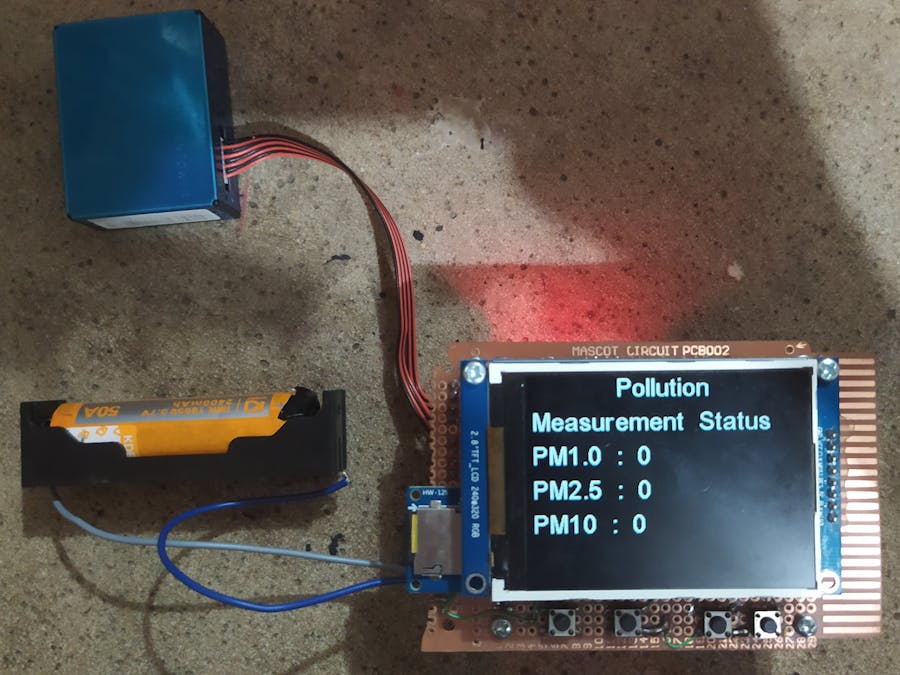
One of the biggest challenge in climate change is reducing the air pollution. The pollution in our atmosphere causing much impact to society, especially in human health. The bad condition of air may lead to several health issue e.g risk of respiratory infections, heart disease and lung cancer. This project aims to increase our awareness to our environment by creating device that will tell the quality of the air in our area.
In order to rebuild the project, we need some hardware and software. For hardware it is required to collect the QuickFeather board from QuickLogic, Air Quality sensor PMS5003 and some additional components/devices like STM32BluePill board, boost converter and some wire jumpers. The firmware for this device was developed using Mbed Studio and Eclipse C/C++.
QuickFeather Module from QuickLogic has huge potential as best buy hardware by combining Logic element and microcontroller which is usually called SoC. This project is beginner friendly, easy to understand.
THE HARDWAREThe hardware was constructed using this diagram below.
From diagram, the device consist of several hardware as mentioned earlier. The QuickFeather will be the main control of system, this module will control the switching power, LCD/SD controller and the Push Button. All of the system is powered by battery 18650 2400 mAh. QuickFeather module will receive data from sensor, parse the data and perform some calculation, then send the realtime data to LCD/SD Controller. It also receive some command by pressing the push button.
Here are some images of my work to combine all of the hardware into single PCB
It is using 8Gb uSD Card as data logger, this gives much space to save data when the device doing the measurement activity. It also need to watch that the sensor PMS5003 needs 5V as the main supply, see datasheet for more information. Because the li-po battery only supply 3.5 - 4.2 V, it is required to put a boost converter to step up the voltage to 5V, in this board using MT3608. On this board also put some of push button to recall some function in Quickfeather module.
SOFTWARESome of software required to compile the program for hardware. To compile LCD/SD controller, it uses Mbed Studio. And to compile the code for Quickfeather, it uses Eclipse C/C++. It is mandatory to install both of the software in order to successfully rebuild this project. Compiling the Quickfeather firmware could be lead to frustration when undefined error occured, so it is important to follow this tutorial step by step. If you dont want to have the problem, compile the code under linux. This will save you from spending some effort.
FIRMWAREHonestly, things going to be much complicated when it goes to low-level (RTL Level), means this could be need much effort. But luckily the Quickfeather support RTOS. So we can run our program on OS Level. To easier to see what happens inside the project firmware, this diagram below explain about it.
The inside of firmware is divided into some tasks, these tasks will do specific function like receive & parse data from sensor, reading push button, prediction calculation and send data to LCD/SD controller. lets begin with push button tasks
## Push Button Task ##
Lets take a look the peripherals of Quickfeather. These push button need GPIO to act. But apparently it has only 8 configurable GPIO, and some of them are already used for some function. At first I could not believe until I read the code. So I did list the unused GPIO pins for my push button.
So I cant do much improvement at OS level because of this limited function of GPIO. I decided to use GPIO 4, 3, 2 for push button, and 0, 2 for power switch. The next things I need to confirm is Interrupt for GPIO, apparently the library still has no function for interrupt callback, which mean I need to do some scanning for GPIO, explained in flowchart below.
The task will always read the state of GPIO, then doing the function when GPIO state is low. Each push button will handle a function. Push button 1, will handle "show data" function, Push button 2 handles "prediction" function, and Push button 3 handle "send data" function.
## UART RX Task ##
This task is related to uart receive of Quickfeather and data transmit from sensor. PMS5003 sent much data with header, this task will detect the header of data and store them to buffer. The task is explained in diagram below.
After required data stored, a function will automatically read data and calculate them for prediction. Then send them to LCD/SD Controller.
## Prediction Calculation ##
For prediction of air quality in this device uses simple linear regression formula, denoted with:
Y = W0 + W1*X
where Y is the calculation result, W0 is starting condition/ constant, W1 is the gradient line, and X is the time.
RESULTThe result of implementation is shown in this figure & video.
- Measurement Data.
I tried to test the sensor measurement by bring the sensor into a bit dusty corner, then I got the result of increment in the value of PM1.0, PM2.5 and PM10.
- Video Demonstration
- Environmental Test. This device is not yet tested outside of house. so the reading of sensor is always small. When it required to outdoor test, then it needs to wrap with waterproof/dustproof enclosure.
- Data Training. Currently the weight of linear regression is not calculated properly due to lack of dataset. The dataset can be gained by outdoor measured data.
- Solid Design. At first, I was about to create the complete board with wifi capability. But I could not realize it due to lack of time to create and test the PCB. Take a look of the 3D design.


Comments
Please log in or sign up to comment.