The automatic door lock was my first creation, and thus, it is a little messy and unorthodox in design. My inspiration came from numerous door-lock inventions I'd seen in movies and tv shows, so I thought it would be cool to make one! (and I need a lock for my door). Overall, the design features a circuit that takes infrared input, from your average Verizon tv remote, and spins a motor one of two ways to open and close the lock.
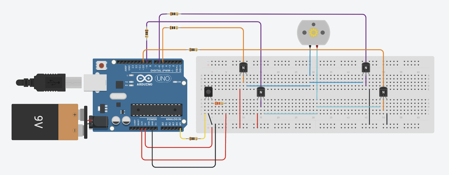
Step One: The CircuitBefore any metal can be put onto the breadboard, it's best to start at the problem you are trying to solve with circuitry. For this fun project, I needed to spin a motor in one direction and then spin it in the opposite direction. I implemented an H-Bridge circuit to solve this issue. This type of circuit, using four transistors, readily switches a motor's spin direction by applying voltages at the gates of certain transistors, which act like switches in my circuit.
Step Two: Assemble The CircuitStart by placing the four transistors and the IR receiver in each of their corners. Before connecting the transistors via jumper wires, connect the five volt pin of the Arduino to the positive, outside strip of the breadboard. Then connect the ground pin of the Arduino to the marked negative outside strip of the breadboard. After finding the emitter, base, and collector regions of each transistor, attach the emitter regions of the two right-side transistors to GND. Connect their bases to the pins on the circuit schematic. Attach the collector regions to opposite sides of the motor. For the two left-side transistors, attach their emitter regions to opposite sides of the motor. Connect their bases to the pins on the circuit schematic. Connect their collectors to 5V. Make sure to put 10 ohm resistors in series with the gates of the transistors and the pins of the Arduino. Now, connect the IR receiver GND and Vcc leads to GND and 5V, respectively. Connect a 10 ohm resistor in series between either connection. Connect a 2.1k ohm resistor in series with the out lead of the IR receiver and analog read pin 5.
Step Three: The SoftwareAbove is a short segment of the code for this device. It uses the % operator to check whether a number is even or odd after each open or close of the lock, which allows the lock to either be set into the lock or unlock stage. When the microcontroller receives a signal that there has been an IR signal, it applies voltages to the gates of the transistors.
This code could definitely be optimized, but seeing as it is my first project, I am happy with its length and complexity.
The code is written so that the mute button on the tv remote is the only button/signal that will open or close the lock. If you are using a different IR transmitter, I recommend using the IR sensor and receiving some signals. Once you have designated the signal you would like to use. Change the "signalValue" from 1799 to your desired integer value.
Note: many IR receivers use hexadecimal to send and receive signals. To get around this, store the signal as another variable under the datatype "int."
Ex. "int expectedSignal = IrReceiver.decodedIRData.decodedRawData;"
Step Four: PlacementThis contraption's components should be glued in place onto the wood board or whatever you choose to build the circuit on. After that, screws, glue, or tape can be used to mount the device onto any door. The external lock piece that the shaft of the lock feeds into should be mounted with screws aligned with the lock. Finally, go build it!
Step Five: DiscoverCheck out my other projects on my dashboard:
- Arduino Uno DIY Drone
- Arduino Smart Traffic Light
- Blindsight: a Wearable Device that Aids the Visually Impaired
- Arduino Functions Library
Check out all of my projects code at my GitHub repository.


_ztBMuBhMHo.jpg?auto=compress%2Cformat&w=48&h=48&fit=fill&bg=ffffff)


Comments
Please log in or sign up to comment.