Ecofill is a cleaning products vending machine. So the users can refill their empty bottles with more product, reducing waste and at lower price. It can dispense precise amounts of the selected product and it is connected to the cloud for configuring it and save a detailed sale log. Among other interesting functions.
Due to the recent COVID-19 pandemic it may be useful for providing antibacterial gel and other sanitizers all the time to the people without the need of human contact, helping to reduce the spreading curve and minimize the economic impact at the same time. Also it can be used to regulate the demand of the products and avoid stock outs, so everybody should be able to obtain their cleaning products.
I had another project in mind but it was impossible for me to complete it because I haven't receive the free hardware yet and it is an essential component for my solution. When I get it I will finish my original project for "The COVID-19 Detect & Protect Challenge".
It can dispense soap for hands, clothes, dishes, antibacterial gel, cream, shampoo, etc. Almost any liquid substance that the peristaltic pump can deal with it. Right now the only way to purchase, is in the machine menu with predefined quantities, but in the future people will be able to use their smartphones to purchase any quantity they want thanks to the MQTT connectivity.
The design is completely modular, so it can be expanded according to each machine and user needs.
How It WorksIt uses the Kemet SS-430L-N proximity sensor to detect when someone is in front of the machine. When no one is near to it, the dispenser light turns off and the LCD brightness gets dimmed. Allowing to save precious energy and increasing the lifetime of the lamp and the LCD. This achieves a real eco-friendly solution.
But as you can see it also helps the machine to stand out. When the lights turn on people notice it, and they got interested in what the machine does. Increasing the chance of making a sale.
Kemet proximity sensor consumes just 800 uA (at maximum), other motion sensors can easily double that number. Also it can detect people up to 5 meters with a field of view of 74 degrees! And it doesn't require bulky lens that pop to the eye, it can also be hidden under certain materials for an elegant design. That helps to keep it protected from the harsh weather and vandalism.
So that makes it ideal for our application, in the video you can see it in action.
Kemet states that this sensors needs at least 3.5V to work, but in my tests it works well with only 3.3V. If you analyze the circuitry in the sensor board you will notice that it has a 3.3V LDO regulator. So there shouldn't be any problem.
For the extra points, you can get it in a ready to use board like the one I received. Or you can get the standalone sensor and embed it in your own design.
Learn more about how it works in the next video:
SkyKontrol Vending System
I have designed a modular solution allowing to use only what you need and opening the door to future improvements. This helps keeping costs low when building your machine and I have published it as an open source design so you will be able to adapt it for your own needs or help me out with improvements.
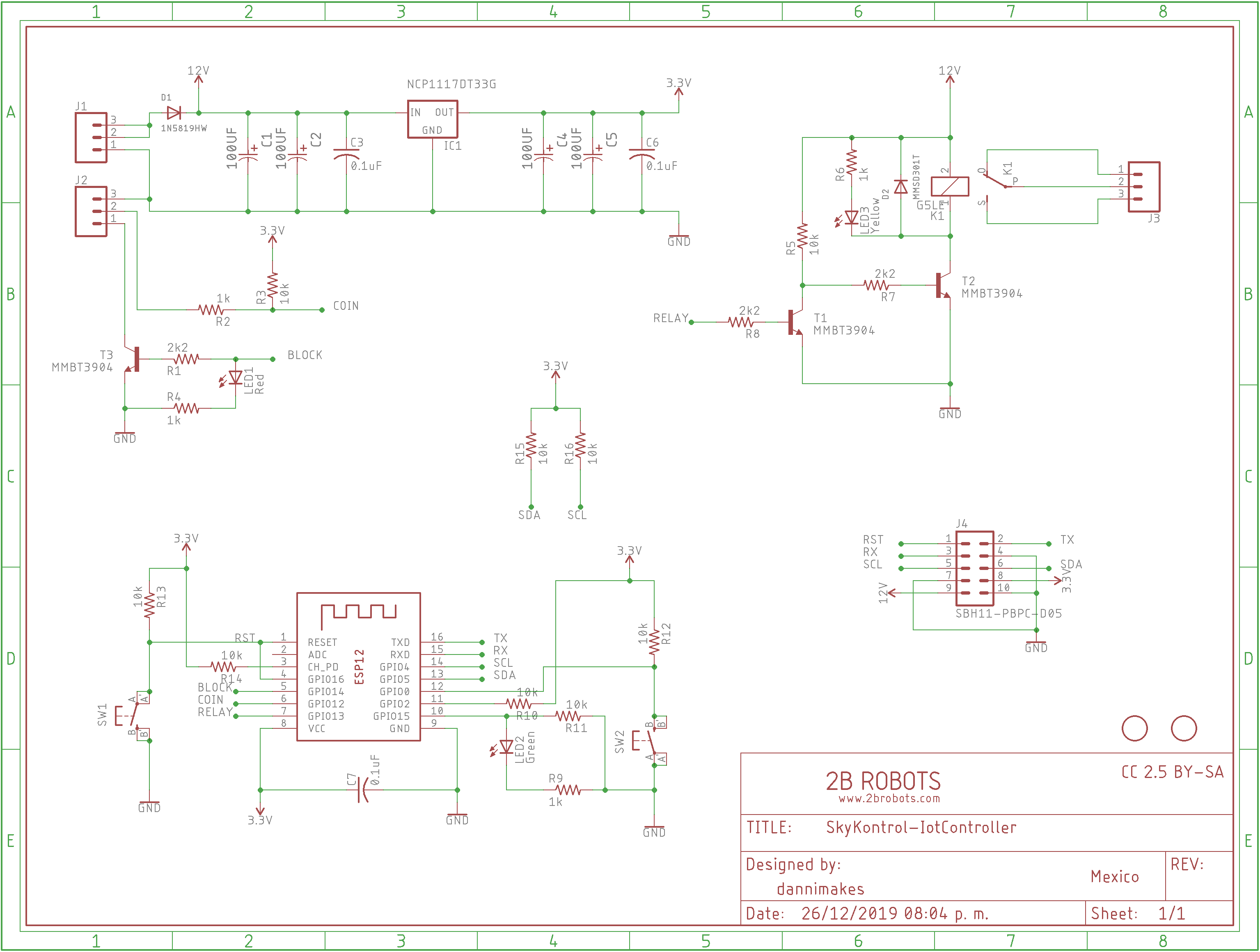
The SkyKontrol system has a main control unit called "IoT Controller", it is based on the ESP8266. A WiFi enabled MCU that can be easily programmed with the Arduino IDE. It has an expansion interface that I call "EXM", it is basically I2C, Serial, Power and the Reset signals exposed over a 10 way ribbon cable. And it allows to debug and program the controller, but also plug any accessory that you wish. As long as you have the code to run it. This main controller also supports OTA updates, so you can add new functionalities and do bug fixes remotely anytime you wish.
This controller detects all the modules that I show in this project and adds or removes functionality based on what is plugged to it. In most of the cases the controller enables cron jobs to read, process and take actions with this extra data from the modules. Also the web platform receives this data and changes the forms based on that. It can also work in standalone mode, this allows to make a single product machine. But all other fancy functions will remain disabled. The data is also stored and synchronized in the modules and the controller, so it can work without internet.
As I told you before it is programmed using the Arduino IDE, just add your Google Cloud API key to enable geolocation and configure your server URL. Then you will be ready to upload it into your board. You can find the full code and module libraries in the project GitHub.
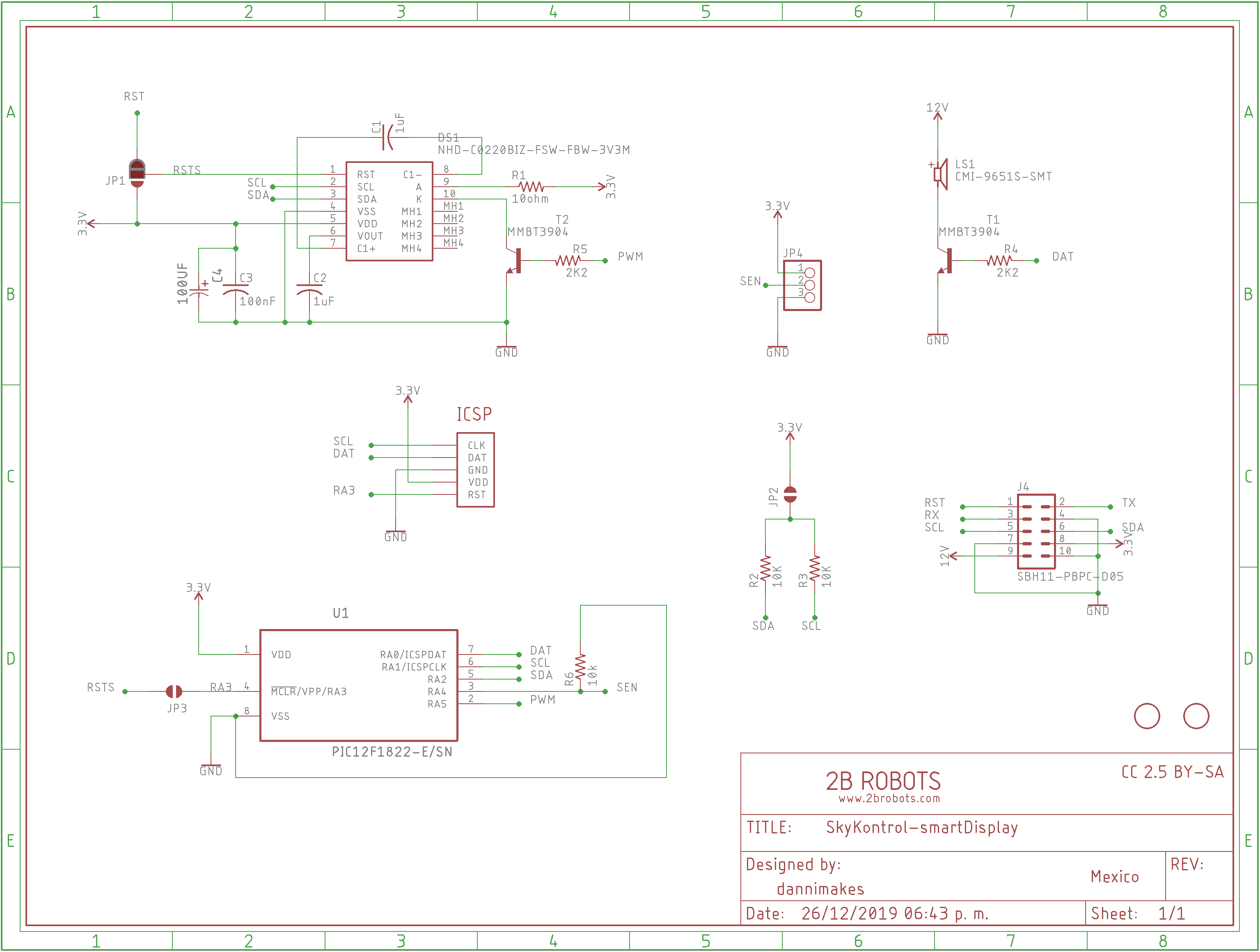
The Smart 20x2 LCD Module is based on the I2C display NHD-C0220 (ST7036i controller chip), there is not a lot to say about that. However the PCB also carries a PIC12F1822 (programmed in MPLAB XC8) as an I2C slave with some interesting functions. Like LCD brightness control, a buzzer for do beepings and the most important, the capability to use the Kemet SS-430L-N Proximity Sensor when it is attached at the side port.
The built-in microcontroller handles a detection program for the Kemet Proximity sensor. When a pulse from the sensor is received it triggers a pulse length validation routine. Each pulse must be at least 197ms long. After 2 good pulses then it confirms a correct detection, sets DETECTED flag and clears timeout counter. And it goes automatically cleared when TIMEOUT runs out. This data is available via I2C to the IoT Controller in order to turn the lamp on and off, and also change the LCD brightness level. After all, the controller is the master and it has total control of all modules with minimal processing time. In general terms, it just coordinates the slaves to work together.
This code section in the Smart LCD Module does the magic behind:
// Global variables declation
volatile union _I2C_buffer {
struct _data {
unsigned char ID;
unsigned char RESET;
unsigned char DETECTED;
unsigned long TIMEOUT;
unsigned long REMAIN;
unsigned int BEEP;
unsigned int BRIGHTNESS;
} data;
unsigned char byte[];
} I2C_buffer;

unsigned char trigger = 0;
unsigned char pulses = 0;
unsigned char pulseLenght = 0;

// Interrupts
void __interrupt isr() {
if (INTCONbits.IOCIF == 1 && IOCAFbits.IOCAF4 == 1) //interrupt on change on RA4 triggered
{
INTCONbits.IOCIE = 0; //disable on change interrupts
trigger = 1;
IOCAFbits.IOCAF4 = 0; //clear interrupt flag
INTCONbits.IOCIE = 1; //enable on change interrupts
}

if (PIR1bits.TMR1IF == 1) //timer1 interrupt, called every 65.536ms
{
INTCONbits.IOCIE = 0; //disable on change interrupts
T1CONbits.TMR1ON = 0; //stop timer1
if (trigger == 1 && PORTAbits.RA4 == 1) //validate pulse lenght when it triggers
{
pulseLenght++;
if (pulseLenght >= 3) //if lenght is enought increment pulses
{
pulseLenght = 0;
trigger = 0;
pulses++;
}
} else {
trigger = 0;
pulseLenght = 0;
}
if (pulses > 2) //if minimun pulses are present then check proximity detectetion
{
I2C_buffer.data.DETECTED = 1;
I2C_buffer.data.REMAIN = I2C_buffer.data.TIMEOUT;
pulses = 0;
}
INTCONbits.IOCIE = 1; //enable on change interrupts
PIR1bits.TMR1IF = 0; //clear interrutp flag
T1CONbits.TMR1ON = 1; //start timer1
}
}

int main(int argc, char** argv) {
while (1) {
asm("CLRWDT");
if (I2C_buffer.data.RESET == 1) {
asm("RESET");
}
PWM_set_duty(I2C_buffer.data.BRIGHTNESS); //set LCD backlight brightness
if (I2C_buffer.data.BEEP > 0) //sound buzzer by requested ms time
{
LATAbits.LATA0 = 1;
I2C_buffer.data.BEEP--;
} else {
LATAbits.LATA0 = 0;
}
if (I2C_buffer.data.DETECTED == 1) //clear proximity detection when timeout is over
{
I2C_buffer.data.REMAIN--;
if (I2C_buffer.data.REMAIN == 0) {
I2C_buffer.data.DETECTED = 0;
}
}
__delay_ms(1);
}
return (EXIT_SUCCESS);
}
With this we are actively preventing false triggerings and clearing motion detection after some time without detecting anything from the sensor. And now our Kemet Proximity sensor is smarter and works over I2C!!!
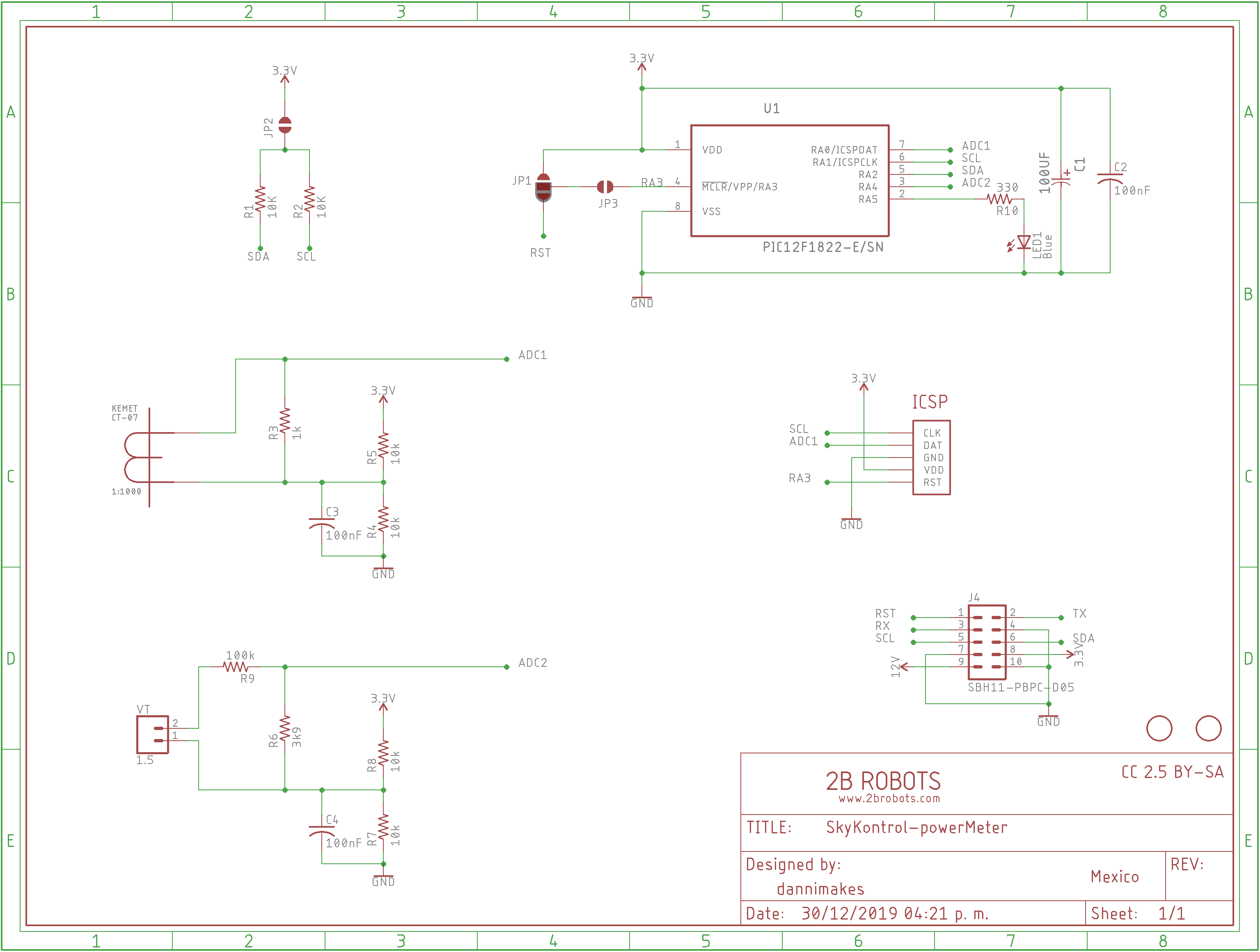
The Power Meter Module is based on the Kemet CT-07-1000 current transformer, it give us the capacity to measure AC currents easily. Combined with AC voltage measurements we are able to estimate consumed power by our machine.
This board is based on the PIC12F1840 and is programmed on MPLAB XC8 as an I2C slave device. It's job is monitor voltage, current and do the math to estimate power. Calculating AC power is a complex job, so the readings main goal is to obtain an approximate reading.
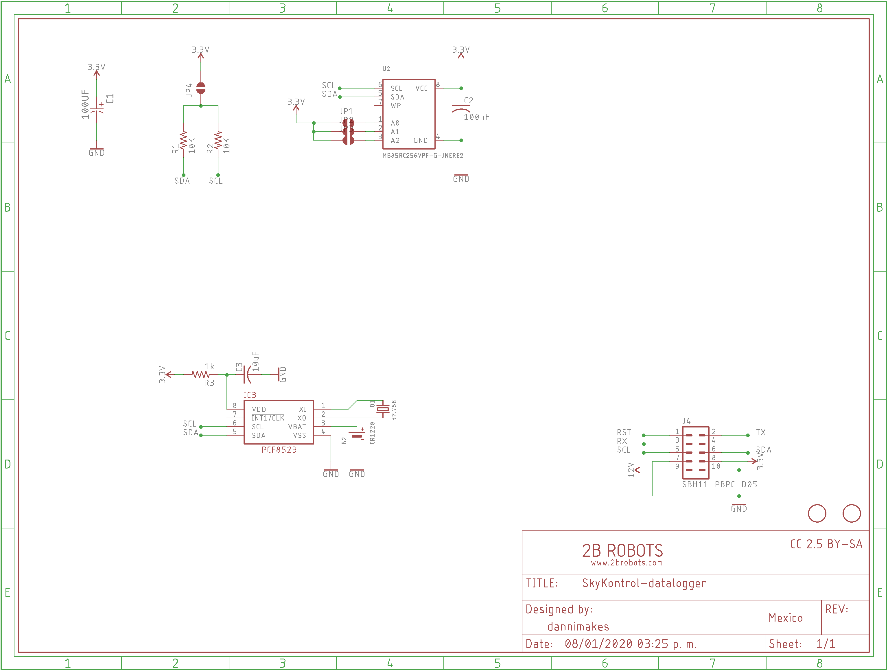
The DataLogger Module contains a PCF8523 RTC and a high speed non-volatile MB85RC256V FRAM memory. Right now it's only job is to hold the date and time to show it on the LCD. But in the future it will be able to store logs when the machine is not connected to the internet, and when the connection is available again it will send all stored data to the server. Avoiding data loss.
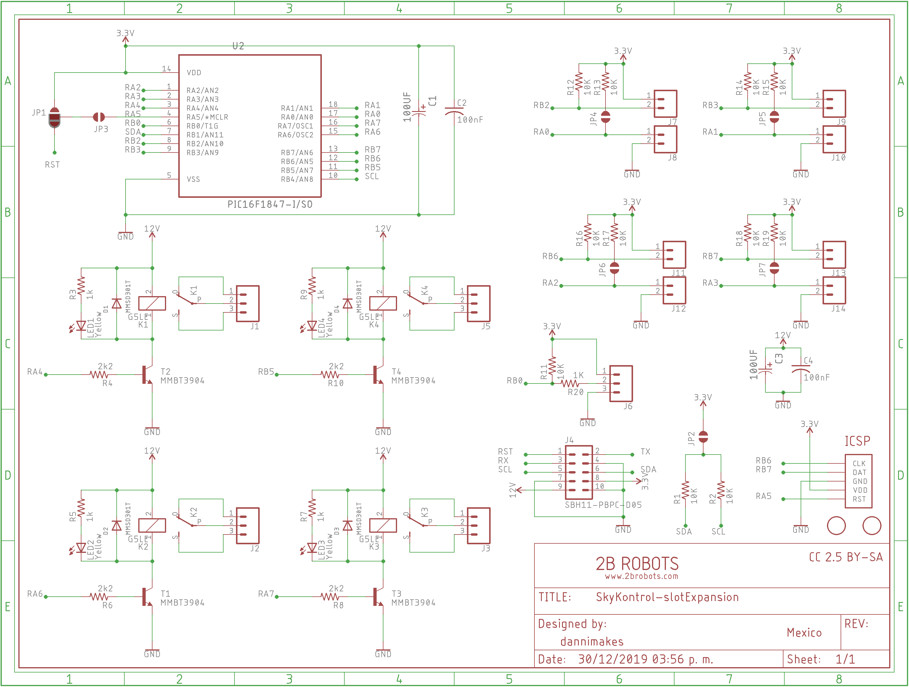
The Slot Expansion Module is used to give the machine the capacity to sale more products. It manages product selection (buttons), product stock level (analog or digital input from a sensor), auto-dispensing capabilities (with precise counting and timing functions) and stores all assigned products data in memory (EEPROM).
This module is based on the PIC16F1847 an it also has been programmed in MPLAB XC8 as an I2C slave device. As you can see, thanks to the modular design we free the IoT Controller from a lot of time consuming tasks, we only need to give the orders to the modules and they will handle the job at their own. An the IoT controller will be free to run other parallel tasks easily without sacrificing performance or taking the risk of an overload with an unexpected fail.
All SkyKontrol modules with a PIC microcontroller requires to be programmed with their respective firmware. I used the PICKit 3 to do that, in the PCB's the programing connector are the 5 smd pads labeled as ICSP. Firmware must be loaded with all jumpers removed and with the EXM cable removed!
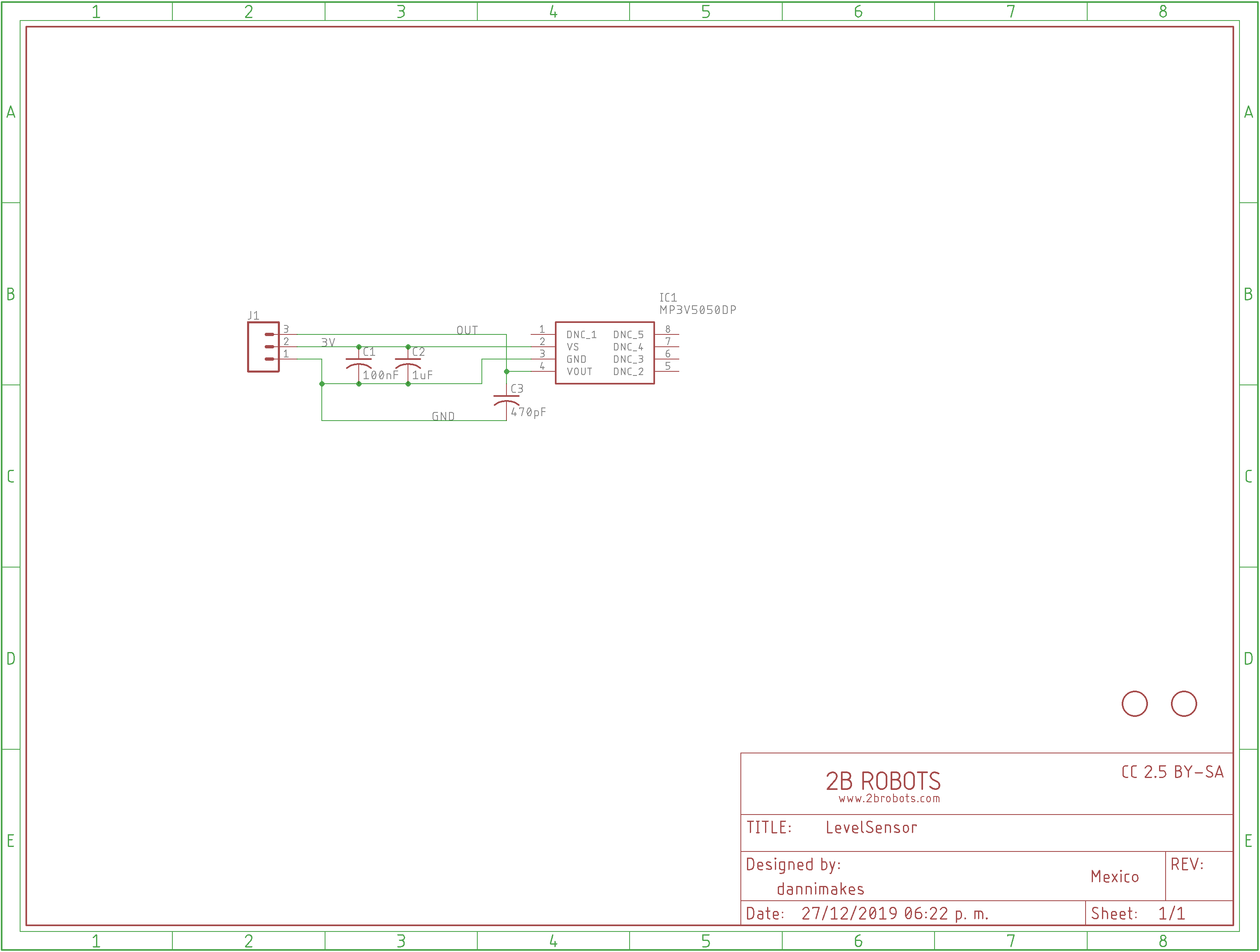
Last but no least is the Pressure Sensor, this is used as a liquid level sensor. It gives us an analog signal proportional to the liquid in the tank. It uses the MP3V5050. Be extra careful when sealing the tube, any leak will be your worst nightmare after a few minutes. Remember that the Level sensor avoids doing sales when the tank doesn't have enough product to dispatch.
Ceramic capacitors in my boards are from Kemet. The PCB's were designed in Autodesk Eagle and PCBway made them. I hand soldered all the components into these boards. You can find all the required files to build your own in the project GitHub, like the schematics, BOM, gerbers and firmware.
I build a prototype using MDF and them I painted it and placed the labels, for a real world application it would require a harder full size cabinet. But for now it will be enough. If you make your own, please share it with us.
I build this thing with my imagination, so I don't have blueprints. However the following images will give you a clear idea of how to build your own.
The boards are secured to the cabinet using plastic standoffs and M3 screws. Then a 10 way ribbon cable is used to join the IoT Controller with the rest of the SkyKontrol EXM modules. This will also give power to them, so no other connection is required unless specified. Just be sure to mach the pin 1 in the connector to the red wire in the ribbon cable. Is super easy to connect. Keep the cable as short as possible to avoid problems.
At the moment I decided to connect only 1 peristaltic pump (They are expensive and I can't afford more right now) and dispense a single product, however the machine can already dispense up to 4 products as showed.
Use proper sized tubes for your pumps and make sure that they seal perfectly and secure it tightly. Otherwise you will end with a gooey mess.
For the Power Supply and Transformer connections are as follows:
- 127 Vac L to Power Supply L. Also connect it to one end of Transformer primary coil. Don't forget to pass this wire through the Kemet CT-07 in the Power Meter Module.
- 127 Vac N to Power Supply N. Also connect it to the other end of Transformer primary coil.
- AC Ground to Power Supply Ground.
- Power Supply V+ to IoT Controller 12v.
- Power Supply V- to IoT Controller GND.
For the Coin Acceptor connections are as follows:
- IoT Controller 12v to Coin Acceptor +12VDC
- IoT Controller GND to Coin Acceptor GND
- IoT Controller CNT to Coin Acceptor CREDIT
- IoT Controller BLK to Coin Acceptor INHIBIT+
For the Lamp (24 Vac) and Power Meter Module connections are as follows:
- Transformer secondary coil to Power Meter VT IN. Each side of the coil to each side of the terminal block. If your transformer has a TAP just ignore it.
- Connect one terminal of your Lamp directly to one end of Transformer secondary coil.
- Connect the other terminal of the Lamp to IoT Controller NO.
- Connect IoT Controller COM to the other end of Transformer secondary coil.
For the Slot Expansion Module are as follows:
- Connect one end of all buttons to Slot Expansion GND.
- Connect the other end of the buttons to the designed role in the Slot Expansion. This are CNL for cancel, use SL1, SL2, SL3 and SL4 for products.
- If you have a Level Sensor connect for each tank sensor the analog output to ST1, ST2, ST3 and ST4 respectively. Also connect your sensors to GND and 3V. If you don't have Level Sensors just solder the on board jumpers close to ADx labels. This will bypass that functionality or also can be used to turn it into a digital input instead of an analog one.
- For the output relays connect COM to V+ on the Power Supply and NO in each relay to V+ in their respective pumps. Connect V- in the pumps to Power Supply V-.
I was having some issues with the buttons triggering randomly when the relays turn on and off, so I added a Kemet 0.1uF ceramic capacitor to each of the buttons to solve the problem. If you also experience electrical noise in the ribbon cable you can try the Kemet ESD-FPL series ferrite cores to to get rid of it.
All the boards have pull-ups integrated, if you are experiencing communication fails you should try enabling or disabling this pull-up resistors on each board. Just solder or unsolder the jumper. Mine has 2 pull-ups enabled to have the correct capacitance in the wire and allow I2C to work without any flaws.
Web Control PanelThe SkyKontrol web interface allows to configure and monitor our machine remotely from anywhere in the world using the power of the internet. We can set the prices, dispensing timer and counter, quantities LCD message an also an out of service mode to disable all sales. We can also see a detailed sales and event log. And there is a summary option automatically generated each month with our total sales and power consumption. One thing to notice is that the main page panel indicates us what modules we have plugged and adapts to it, showing us only the required configuration. We can also see where our machine is located.
This platform is also available in the project GitHub, so you will be able to deploy it in your own LAMP (Linux, Apache, MySQL and PHP) web server. You can also use a Raspberry Pi to make one.
Mine is a combination, I use a professional hosting service to power the platform. However the MQTT communication is powered by a Raspberry Pi with a Mosquitto Broker. This last step is actually not required at the moment, but will be used in the future to allow instantaneous communications with the machines and enable the possibility to purchase directly from any smartphone. So keep it in mind.
To install it you only need to download the files in the GitHub and place them into your server. Then connect to your database and set up a new one using the included setup SQL file.
After that fill the important data in the DB tables like your board MAC address, user, password and products.
There is a file called "credentials.php", in this file add all the required data and you will be ready to go. To enable the location map, you will also need a Google Cloud API key.
You can edit them with a simple text editor or use Visual Studio like me for a more professional approach.
Also you will need to add PHP files in the "scripts" folder to a cron job to run at desired times. I recommend the following configuration:
0 5 * * * php -q /skykontrol/scripts/cleanSales.php --cron >/dev/null 2>&1
15 4 * * * php -q /skykontrol/scripts/cleanEvents.php --cron >/dev/null 2>&1
0 3 2 * * php -q /skykontrol/scripts/generateSummaries.php --cron >/dev/null 2>&1
0 2 1 * * php -q /skykontrol/scripts/cleanSummaries.php --cron >/dev/null 2>&1
0 1 * * * php -q /skykontrol/scripts/cleanPower.php --cron >/dev/null 2>&1
There is also a Console option that will connect to your machine via MQTT to do useful configurations and diagnostics. However right now is still in development and is not ready to be used. So there is nothing more to configure for now.
ConclusionThank you very much for reading my project, and if you have any questions don't hesitate to ask me. As you can see it is very complex and large to document project, so please help me to know how I can improve this document.
I hope you like it. And if you have any ideas, improvements or suggestions I will be happy to hear them.
Have a nice day :)




Comments
Please log in or sign up to comment.