Hardware components | ||||||
_ztBMuBhMHo.jpg?auto=compress%2Cformat&w=48&h=48&fit=fill&bg=ffffff) |
| × | 2 | |||
| × | 1 | ||||
| × | 1 | ||||
| × | 1 | ||||
 |
| × | 1 | |||
 |
| × | 5 | |||
| × | 1 | ||||
| × | 1 | ||||
Hand tools and fabrication machines | ||||||
 |
| |||||
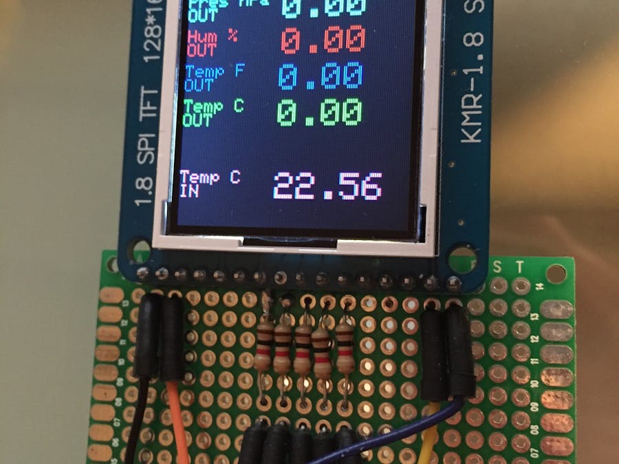
Starting from my previous project v.1.0 I added RF communication, a TFT display and a Dallas temperature sensor.
The transmit circuit will be encapsulated inside a Solar Panel that can power the circuit and will be placed out of the window.
For the solar part, I bought an already prepared shield on ebay and I just connect my circuit using USB.
The recover circuit will be encapsulated in a shield (that I didn't create yet) to be added inside the house.
For energy consumption reduction, I will upload my sketch on an Arduino Nano as soon as I will receive it and, I will enable low consumption library.
/* ------------------------------------------------------------------------------- */
// Weather Station v1.3
//Transmitter part

#include <Wire.h> //Management of wire connections
#include <VirtualWire.h> //Management of Virtual Wire for RF transmission
#include "cactus_io_BME280_I2C.h" //Manage BME280 temp, humidity, pressure sensor
#include <stdlib.h> //Library for string conversion
#include <LowPower.h> //Library for energy efficency

// Create the BME280 object
BME280_I2C bme;              // I2C using default 0x77
//BME280_I2C bme(0x76);  // I2C using address 0x76
//int backLight = 13;    // pin 13 will control the backlight managed by button

const int TX_DIO_Pin = 7; //Definition of Transmission DATA PIN
static char outstr[10]="0.00"; //Buffer String for convert BME readed values
static char message[12]={0};

void setup()
{
  Serial.begin(9600); //Serial communication 9600
  if (!bme.begin()) {           //Check if BME280 is connected and working
    Serial.println("Could not find a valid BME280 sensor, check wiring!");
    while (1);
  }

  bme.setTempCal(-1);           //Claibrate BME280 sensor
  initialize_transmitter();     //Initialize transmitter
}


void loop()                     //Main looping code
{
  bme.readSensor();

  dtostrf(bme.getPressure_MB(), 6, 2, outstr);                            //Read Pressure and convert in string

 strcat(message,"P");
 strcat(message,outstr);

 vw_send((int8_t *)message, strlen(message));                              //Transmitt Pressure
 //Serial.println(bme.getPressure_MB());
 message[0] = (char)0;
 delay(1000);                                                             //Delay for transmission

 dtostrf(bme.getHumidity(), 5, 2, outstr);                               //Read Humidity and convert in string

  strcat(message,"H");
  strcat(message,outstr);
  vw_send((int8_t *)message, strlen(message));                              //Transmitt Humidity
  //Serial.println(bme.getHumidity());
  message[0] = (char)0;
  delay(1000);                                                             //Delay for transmission

 dtostrf(bme.getTemperature_C(), 5, 2, outstr);                          //Read Temperature in C and convert in string

  strcat(message,"T");
  strcat(message,outstr);
  vw_send((int8_t *)message, strlen(message));                              //Transmitt Temperature in C
  //Serial.println(bme.getTemperature_C());
  message[0] = (char)0;
  delay(1000);                                                             //Delay for transmission

 dtostrf(bme.getTemperature_F(), 5, 2, outstr);                          //Read Temperature in F and convert in string

  strcat(message,"F");
  strcat(message,outstr);
  vw_send((int8_t *)message, strlen(message));                              //Transmitt Temperature in F
  //Serial.println(bme.getTemperature_F());
  message[0] = (char)0;
  delay(1000);                                                             //Delay for transmission

  LowPower.powerDown(SLEEP_8S, ADC_OFF, BOD_OFF); // instead of delay(3000) ;
  //delay(3000);                                                            //just here to slow down the output so it is easier to read
}

void initialize_transmitter() {
  vw_set_tx_pin(TX_DIO_Pin);  // Initialises the DIO pin used to send data to the Tx module
  vw_set_ptt_inverted(true);  // Set the transmit logic level (LOW = transmit for this version of module)
  vw_setup(2000);             // Transmit at 2000 bits per second
}


/* ------------------------------------------------------------------------------- */
/* ------------------------------------------------------------------------------- */
// Weather Station v1.3
//Receiver code with LCD management
// Andrea Martignoni
// martignoni.a@gmail.com

/* ------------------------------------------------------------------------------- */

#include <LiquidCrystal.h> //Liquid Cristal Mgt Lib
#include <Wire.h> //Management of wire connections
#include <VirtualWire.h> //Virtual Wire for sensor reading
#include <stdlib.h> //Library for string conversion
#include <Adafruit_GFX.h>    // Core graphics library
#include <Adafruit_ST7735.h> // Hardware-specific library
#include <SPI.h>

#include <OneWire.h>
#include <DallasTemperature.h> //Dallas Temperature Sensor

// Data wire is plugged into pin 4 on the Arduino
#define ONE_WIRE_BUS 4
// Setup a oneWire instance to communicate with any OneWire devices (not just Maxim/Dallas temperature ICs)
OneWire oneWire(ONE_WIRE_BUS);

// Pass our oneWire reference to Dallas Temperature.
DallasTemperature sensors(&oneWire);

// Pins definition for LCD
#define TFT_CS     10
#define TFT_RST    9
#define TFT_DC     8
Adafruit_ST7735 tft = Adafruit_ST7735(TFT_CS,  TFT_DC, TFT_RST);
#define TFT_SCLK 13   // set these to be whatever pins you like!
#define TFT_MOSI 11   // set these to be whatever pins you like!

const int RX_DIO_Pin = 2; //Pin for RX receiver
int received;
float rec;
static char outstr[10];
String message;
char swith;
char* out;

void setup() {

  Serial.begin(9600);

  sensors.begin();
  // Use this initializer if you're using a 1.8" TFT
  tft.initR(INITR_BLACKTAB);   // initialize a ST7735S chip, black tab

  uint16_t time = millis();

  tft.fillScreen(ST7735_BLACK);
  time = millis() - time;

  // large block of text
  tft.fillScreen(ST7735_BLACK); //initialize the screen in black
  tft.setRotation(90); //rotate the screen for my convenience
  testdrawtext("Hello!", ST7735_MAGENTA, 0,0,3); //Title of the screen
  delay(1000); //1 sec delay
  initialize_receiver(); //initialize Receiver
  //Create fixed graphic for the screen
  testdrawtext("Pres hPa", ST7735_YELLOW, 0,29,1);
  testdrawtext("OUT", ST7735_YELLOW, 0,37,1);
  testdrawtext("Hum %", ST7735_BLUE, 0,49,1);
  testdrawtext("OUT", ST7735_BLUE, 0,57,1);
  testdrawtext("Temp F", ST7735_RED, 0,69,1);
  testdrawtext("OUT", ST7735_RED, 0,77,1);
  testdrawtext("Temp C", ST7735_GREEN, 0,89,1);
  testdrawtext("OUT", ST7735_GREEN, 0,97,1);
  testdrawtext("Temp C", ST7735_MAGENTA, 0,129,1);
  testdrawtext("IN ", ST7735_MAGENTA, 0,137,1);
}

/* Main program */
void loop() {
  uint8_t buf[VW_MAX_MESSAGE_LEN]; //Buffer for received message
  uint8_t buflen = VW_MAX_MESSAGE_LEN; //lenght of message
  vw_get_message(buf, &buflen); //read message
  message = (char*)buf; //temporary string
  Serial.print(message); //check on serial received message just for wire and soldering check
  swith=message[0]; //check which kind of value has been received

  switch (swith) { //based on kind of message pool
    case 'P':
      //clean received string
      message=message.substring(1,7);
      testdrawtext(message, ST7735_YELLOW, 55,30,2);
      break;

    case 'H':
      //clean received string
      message=message.substring(1,6);
      testdrawtext(message, ST7735_BLUE, 55,50,2);
      break;

    case 'F':
      //clean received string
      message=message.substring(1,6);
      testdrawtext(message, ST7735_RED, 55,70,2);
      break;

    case 'T':
      //clean received string
      message=message.substring(1,6);
      testdrawtext(message, ST7735_GREEN, 55,90,2);
      break;

    default:
      // if messages are not coming from receiver
      testdrawtext("N/A", ST7735_YELLOW, 55,30,2);
      testdrawtext("N/A", ST7735_BLUE, 55,50,2);
      testdrawtext("N/A", ST7735_RED, 55,70,2);
      testdrawtext("N/A", ST7735_GREEN, 55,90,2);
    break;
  }

  sensors.requestTemperatures();  //Read temperature from internal sensor
  testdrawtext(dtostrf(sensors.getTempCByIndex(0),3,2,outstr), ST7735_MAGENTA, 55,130,2);
  delay(200);

}


/* DO NOT EDIT BELOW */

void initialize_receiver() {
  /* Initialises the DIO pin used to receive data from the Rx module */
  vw_set_rx_pin(RX_DIO_Pin);
  /* Receive at 2000 bits per second */
  vw_setup(2000);
  /* Enable the receiver */
  vw_rx_start();
}

void testdrawtext(String text, uint16_t color, int x, int y, int textSize) {
  tft.setCursor(x, y);
  tft.setTextColor(color, ST7735_BLACK);
  tft.setTextSize(textSize);
  tft.setTextWrap(true);
  tft.print(text);
}


Comments
Please log in or sign up to comment.