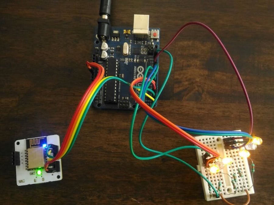
Continuously running a tube light in your home even though you do not need it or require a dim light not only cost a lot but sometimes irritates a person. It would be awesome if you would be able to control the brightness of tube light at a your finger tips. Isn't it! Today this project will help you to develop a small prototype so that you can control your tube light at home via few commands. Here we will control max of six LEDs using Bolt and Arduino. The brightness is controlled using the 6 PWM channels provided on the Arduino unit.
Gathering all the required componentsAll the components required for the project are mentioned below and are easily available in market at reasonable price.
1. Bolt
2. Arduino Uno
3. LED
4. Resistor (330 Ohms)
5. Breadboard
6. Jumper Wires (Male/Male)
7. USB Cable for Arduino
Bolt IoT platform gives you the capability to control your devices and collect data from IoT devices safely and securely no matter where you are. Get actionable insights by deploying machine learning algorithms with just a few clicks to detect anomalies as well as predict sensor values. To know more visit boltiot.com.
Pulse-width modulationIt is used for controlling the amplitude of digital signals in order to control devices and applications requiring power or electricity. It essentially controls the amount of power, in the perspective of the voltage component, that is given to a device by cycling the on-and-off phases of a digital signal quickly and varying the width of the "on" phase or duty cycle. To the device, this would appear as a steady power input with an average voltage value, which is the result of the percentage of the on time. Know more here.
Assembling the hardware1. Gather all components and check the LED's are working fine or not.
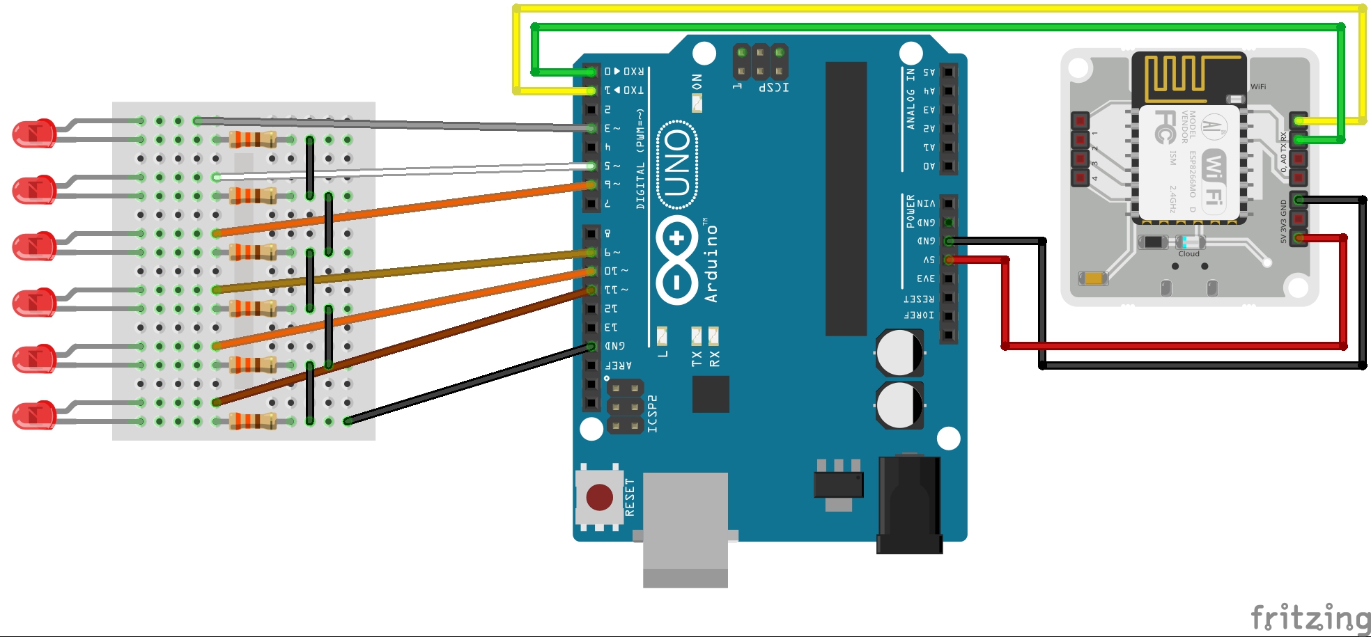
2. Connect cathode of LEDs to GND line and anode to a 330 Ohm resistor in series.
3. Connect the other end of the resistor to the 6 PWM channels (i.e. pins 3, 5, 6, 9, 10 and 11).
4. Connect the GND of Arduino to the GND line of breadboard.
5. Connect the Tx and Rx of the Bolt to the Rx and Tx of the Arduino respectively.
6. Finally, connect the 5V pin of the bolt to the 5V pin of Arduino and GND of Bolt to the GND of Arduino.
NOTE: Referto the schematics for any guidance.
1. Go to cloud.boltiot.com and sign up to create an account.
2. Download BoltIot App in your mobile and login into your account and add your new Bolt device. Know more at how to add the bolt device.
3. Get your Bolt device ID as shown below.
4. To get the API key for your account at cloud, goto API and click on enable as shown.
NOTE: The above API key and Bolt device ID is very important do not share with anyone.
API and Bolt Cloud APIAn application programming interface (API) is a particular set of rules ('code') and specifications that software programs can follow to communicate with each other. It serves as an interface between different software programs and facilitates their interaction, similar to the way the user interface facilitates interaction between humans and computers.
The Bolt Cloud API provides an interface for communication between the Bolt devices and any 3rd party system e.g. mobile application, web server, python programs etc. The API contains very intuitive control, monitoring, communication and utility functions for the Bolt Devices connected to your account.
To use the API calls for Bolt Cloud we will require the Bolt device ID and the API key we got before.The general syntax for the API call from a web browser looks like the one given below:
https://cloud.boltiot.com/remote/your_api_key/command?¶m1=...¶m2=...&deviceName=BOLTXXXXX
where <your_api_key> is replaced by the Bolt Cloud API and <BOLTXXXXX> with the Bolt device ID.For eg-
https://cloud.boltiot.com/remote/0e17f7d8-c1a3-4692-b667-7251175f7ab6/restart?&deviceName=BOLT9161541
To know more click here.
Code for Arduino1. Download the boltiot-arduino-helper library from GitHub and add it to the Arduino library. To download click here.
2. Upload the code provide below to the Arduino Uno.
NOTE:RemovetheTxandTxconnectionbetweenBoltandArduinobeforeuploading.
API calls for controlling brightnessFor controlling the led brightness using the API call we will use the UART API's of the Bolt Cloud. First, initialise the serial communication between Bolt and Arduino via serialBegin API call as given:
https://cloud.boltiot.com/remote/0e17f7d8-c1a3-4692-b667-7251175f7ab6/serialBegin?baud=9600&deviceName=BOLT13819450
For turning the led ON with certain brightness we will require the serialWrite API call as given:
https://cloud.boltiot.com/remote/0e17f7d8-c1a3-4692-b667-7251175f7ab6/serialWrite?data=ON
We have to replace <led number> and <PWM values> with 2 parameters, first contains the pin number of the led whose brightness has to be changed and the second contains the value for the PWM corresponding to the same led.
NOTE: Both the parameters must be separated by ' '(space) character in between them and also and the end of the data variable.
For eg- If you want to control the brightness of the led at pins 3 (i.e led 1) with PWM value of 120 then the data variable in the API call will be given by:
'data=ON 1 120 '
Note: There is space at the end of the data variable also.
To get the response of each of the serialWrite API call we will use serialRead API just after that. It is given by:
https://cloud.boltiot.com/remote/0e17f7d8-c1a3-4692-b667-7251175f7ab6/serialRead?till=10&deviceName=BOLT8795377
NOTE: InalltheaboveAPIcallsreplace the API key and the Bolt device ID with the one you got from Bolt account.
Working principleThe working principle is very simple, the Arduino continuously check for the serial command received from Bolt. If the command string matches with "ON" it performs the corresponding function.
When it receives the ON command followed by the data variable then the Arduino first stores the pin number and PWM value from the data variable. The Arduino then checks whether the pin number is within the range or not. if no it sends a response back saying 'pin number should be b/w 1 and 6'.
And if everything is right it performs the analogWrite command to the pin with the corresponding PWM value in order to control the control the brightness. After controlling the brightness, it sends a response back saying '"Pin <pin> was set to pwm value <pwm>"
Hence in this way a user can control brightness of max 6 leds at a given time.


_ztBMuBhMHo.jpg?auto=compress%2Cformat&w=48&h=48&fit=fill&bg=ffffff)


Comments
Please log in or sign up to comment.