This is an introductory electrical engineering project for my Engi 301 Intro to Practical Electrical Engineering class at Rice University.
MotivationDisabled people who cannot speak use sign language as one of their primary modes of communication. Because I do not understand sign language, in any encounters with such people I need the help of an interpreter to understand what they are saying. This discourages communication as it requires the non-speaking person to always have a 3rd person interpreter present along with them. Thus I wanted to create an electronic device that would detect the symbols someone makes with their hands and output a character on a screen that could be understood by those who have not learned sign language. I also wanted to include the component of hand movement and orientation for more complex signing. Although I was unable to achieve this in this iteration of the project, in the future I will try to get my device to interpret the gesture of a number (drawing a number in the air). Signing uses both fingers and hand movements, and my goal with this project is to begin to interpret and translate these movements to output words and numbers. I have taken inspiration from these two projects:- https://www.hackster.io/sachin0987/handtalk-a-smart-handglove-interpreter-71fa7d- https://www.hackster.io/andrei-mitrofan/no-touch-gesture-calculator-40e7d4
HardwareThe hardware components used in this project are explained below. A PocketBeagle was used as the microcontroller. For reference, below is the pinout diagram that shows the function of each pin on the PocketBeagle.
The header pins of the flex sensor are very fragile and too small to fit in female jumper wires. Thus, my first step was to solder more durable header pins onto the flex sensor as shown in the image.
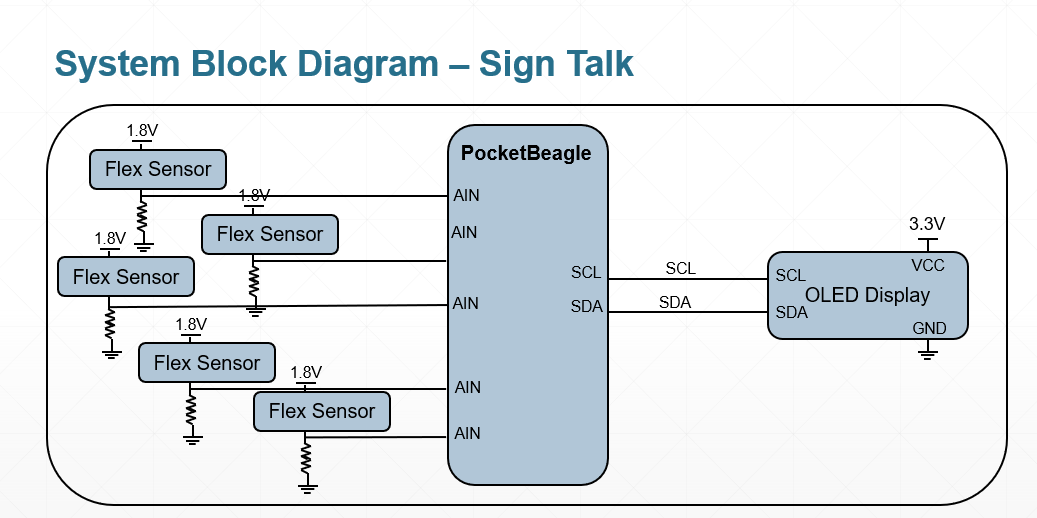
Next I wanted to check whether and how the flex sensors worked so I wired one flex sensor as shown in the system block diagram in the schematics section of this page. I used a voltage divider circuit to read the analog voltage value output from the sensor. This is because the flex sensor works essentially like a potentiometer. A 10k resistor was used.
The following pins on the PocketBeagle were used for this flex sensor voltage divider circuit:
- P1_18 AIN1.8VREF+ to first sensor pin (provides power)
- AIN0 to second sensor pin
- P1_17 AIN1.8VREF- to 10k resistor (grounding)
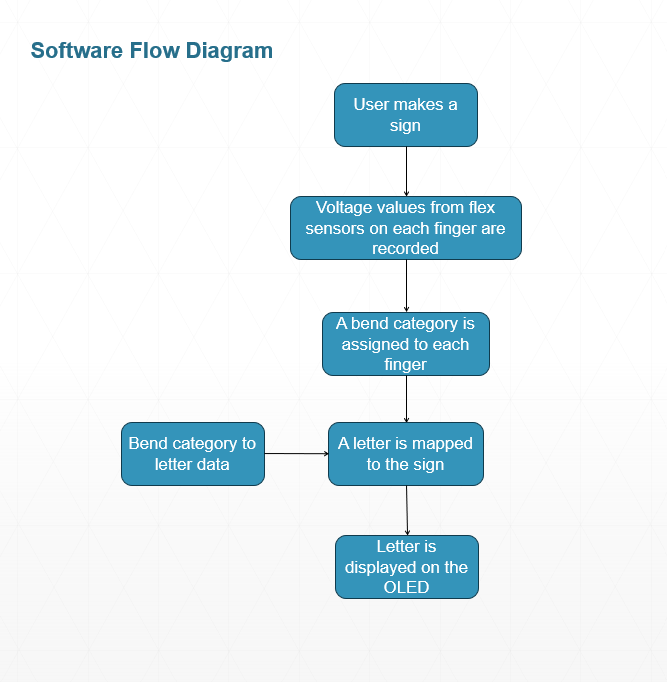
I found that when the flex sensor was not flexed at all, the output value was 1023. Flexing the sensor (or, analogously, bending a finger) decreased the value. I then determined that the the approximate “medium” bend values were from 600-900 and the “low” (maximal bend) values were from 100-600. Values above 900 indicated “high” (minimal bend). These values and threshold will be crucial for use in code for categorization and mapping of each sign to a letter.
I then connected all 5 flex sensors to the pocket beagle. The 5 analog input pins used are:
- P1_19 AIN0
- P1_23 AIN2
- P1_25 AIN3
- P1_27 AIN4
- P1_2 AIN6
My PocketBeagle’s P1_21 AIN1 pin was damaged because I had initially powered the circuit with 5V instead of 1.8V and had accidentally moved circuit components for that pin while power was still running, which had damaged that pin. Thus I used the P1_2 AIN6 pin instead.
I first soldered header pins to the OLED display so that I could use it with a breadboard.
I connected the OLED pins to the PocketBeagle in the following way:
- SCL to P2_9
- SDA to P2_11
- VCC to P2_23
- GND to P2_21
After installing some packages to cloud9 (software IDE) and running some source code, I was able to get the OLED to draw text. Details about the code and setup are in the github repository linked in the software section of this page.
Glove Form FactorIn order to house the sensors on the glove in a way that the sensors bend proportional to the finger, I cut small slits along each finger on the glove. I then fit the sensors through these slits and used tape to secure the top and bottom ends of the sensor to the glove.
All the python files and setup instructions in the Github link must be downloaded and installed through the PocketBeagle cloud9 IDE.
ChallengesThere were numerous challenges for me along the way because it was my first time working on an embedded systems project. First, I had to figure out how to properly use a voltage divider circuit and what resistor value I should use in order to get good analog values from the sensors while also not frying the pins from too much voltage supply. Furthermore, I also had to understand the several code components I had to install in order for my OLED to work as intended. Overall, I think this project gave me a very good starting point for learning embedded systems and this is definitely a field I want to keep studying and learning about.
Future WorkThe major improvement I want to incorporate is that I want to program some sort of timer system or a similar algorithm so that a person could sign individual letters to make a whole word. This allows for more flexibility and range in what someone is signing instead of a fixed number of specified signals. I also plan to incorporate a help/SOS function with a buzzer. Furthermore, my original plan was to include an IMU that could identify gestures and movement of the hand itself, so I hope to work on that aspect as well. I also want to expand my dataset, or increase the number of signs that this device is able to correctly classify.
AcknowledgementsI would like to thank my ENGI 301 professor Erik Welsh for helping me and guiding me so much through all the challenges and learning of this project.


Comments
Please log in or sign up to comment.