


UPDATE MAY 2020: MARK Kickstarter Campaign is now live!
In the previous article in series The Road from Line Following to Lane Following we have explored how to use computer vision to make our robocar (MARK by TinkerGen STEM Education) follow the lines.
It was an interesting exercise and line following can be considered "a staple" of teaching robotics to younger students. Unfortunately the algorithm for line following is too simplistic and is very different from what is actually being used nowadays in pilot assist systems and (developing) self-driving cars. So, we'll take a step further and research into lane following by using two distinctly different approaches: hard-coded OpenMV pipeline and Deep Learning based approach.
UPDATED 03/29/2022. I try my best to keep my articles updated on a regular basis and based on your feedback from YouTube/Hackster comments section. If you'd like to show your support and appreciation for these efforts, consider buying me a coffee (or a pizza) :) .
You might be familiar with lane following, since it is relatively mature technology and is being used in consumer vehicles, where it is called Lane Keep Assist System (LKAS). Quick Google search shows, that almost every major car manufacturer have LKAS system for modern cars (Volvo Pilot Assist, Volkswagen driver assistance pack plus, Audi Active Lane Assist, Tesla's Autopilot, etc).
A few years ago many of these systems have been relying on image processing techniques called hough transform and canny edge detection techniques and then more advanced versions of LKAS were developed using Deep Learning (source).
LKAS system would consist of two components:
- Perception (lane detection)
- Path/Motion Planning (steering)
A typical way to implement perception component is following pipeline:
- Isolate the lane based on color or ROI (optional)
- Edge detection for detecting edges of the lanes
- Detect line segments
- Combine line segments into two lanes
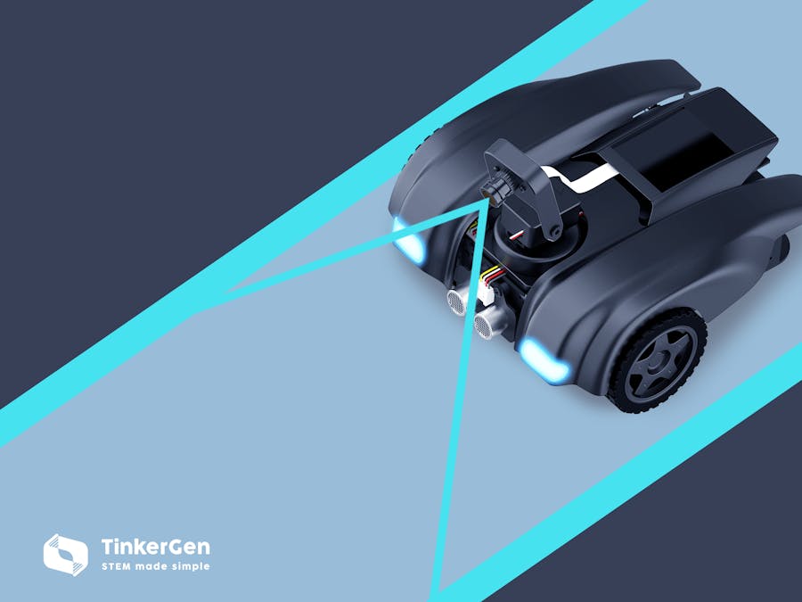
For this article we will use MARK(Make A Robot Kit) made by TinkerGen Education, it is a mobile robotic platform built around cyberEye mainboard with K210 chip. K210's micropython firmware has full-featured OpenMV support, albeit according to MaixPy Github repository, OpenMV components are not updated in timely fashion.
We'll start by assigning ROI(region of interest) of half of the image height. I have experimented with applying line detection to 3 different images:
roi=(0,120,320,240)
img = img.binary([high_threshold]) #choose one
img = img.laplacian(1, add =2, mul =2) #choose one- original RGB image
- edge image(with laplacian filter applied)
- image after applying binary threshold (to filter out pixels that are darker than threshold)
Empirically I found that binary threshold works the best. Laplacian filter yielded no significant improvement in quality of line detection and original RGB image had too much noise in it for line detection algorithm.
Next we apply img.find_lines() function on binary image - that function finds infinite lines in the image. There are two relevant function implemented in OpenMV - find_lines() and find_line_segments(). From this thread on OpenMV forum it seems, that find_line_segments might be more suitable for lane detection, but unfortunately it is way too slow to be run even for a cropped image in current version of MaixPy.
for l in img.find_lines(roi=roi,threshold = 2000,x_stride=2, y_stride=1):After applying img_find_lines() function to binary image, we cycle through all the lines found in the region of interest and 1)filter out horizontal lines 2)find the left lane and right lane(the lines closest to image border on the left and right).
for l in img.find_lines(roi=roi,threshold = 2000,x_stride=2, y_stride=1):
    if l.theta() !=89 and l.theta() != 0:
        #a = img.draw_line(l.line(), color = (0, 0, 255), thickness=3)
        if l.x1() >= max_left:
            max_left = l.x1()
            max_left_line = l
        if l.x2() <= max_right:
            max_right = l.x2()
            max_right_line = l
if max_right_line != 0:
    a = img.draw_line(max_right_line.line(), color = (255, 0, 0), thickness=3)
    line_right = max_right_line.x2()
else:
    line_right = 0
if max_left_line != 0:
    a = img.draw_line(max_left_line.line(), color = (255, 0, 0), thickness=3)
    line_left = max_left_line.x1()
else:
    line_left = 0

lane_center = (line_left+line_right)//2
print(lane_center)
print(line_left)
print(line_right)
a = img.draw_arrow(160, 240, lane_center, 120, (0,0,255), thickness=3)
We do some drawing for easier debugging - here is sample image we can get with this approach, the arrow points at the center between the lanes.
Now, when we know the point where do we need to steer, we can apply the formula that we discussed in the previous article to generate the deflection angle for us and plug it into steering function, that we already conveniently implemented in MARK firmware.
deflection_angle = -math.atan((lane_center-160)/120)
deflection_angle = math.degrees(deflection_angle)//2
Off we go!
From this experiment it is clear that some improvements can be made:
1) Lane lines should be slightly more narrow, since a lot of the time the algorithm cannot detect both lines in lower part of the ROI
2) find_line_segments() function could be more useful for lane detection purpose. It has been updated in main OpenMV repository, but that hasn't been pulled to MaixPy repository yet.
3) I spent almost whole day tweaking parameters for line detection and trying different image processing methods. While in the end it was possible to achieve acceptable results, any major change in environment (especially the light) affects carefully tuned parameters. Perhaps that's why we had the first driverless car to cross the US in 1995 (98.2% was autonomously controlled, Carnegie Mellon University's Navlab), but haven't got anywhere close to self-driving until recently.
If only there was a way we could make a sort of algorithm that could learn from large amount of driving data, comprised of steering direction and video frames... That would be really convenient since we could gather the data from different environments and have the system learn the rule for choosing the driving direction from data. Ah, that would be really great to have such an algorithm!
Well, we do.
I'm obviously talking about Machine learning and it's subset, Deep Learning. We can frame the steering task as a classification task: steer left/right or go forward, for every frame of the image. Conveniently for us, MARK's control chip, K210 has a co-processor that can accelerate inference of common convolutional network operations.
First and the most time-consuming step will be getting the training data. I wrote a micropython script (see the code section), that allowed me to steer MARK with two push-buttons and for every movement frame recorded that frame in the video file and simultaneously wrote the number of the frame and action taken in the text file on SD card. After transferring the video and text files to computer I used convert.py script to process the frames into pictures and divide them into three groups: steer left/steer right/go forward. Then I uploaded data to my Google Drive and used aXeleRate, Keras-based framework for AI on the Edge to train a Mobilenet (alpha=0.25) based classifier and automatically convert trained model into.kmodel format, you can browse the Colab notebook here.
aXeleRate also can be used to train models and convert them to.tflite format, if you want to recreate similar experiment with Raspberry Pi or any other mainboard, that can support Tensorflow Lite. Then I used a simple script that runs classification on the image from the camera and outputs probabilities for each class - then steers MARK according to the class with highest probability.
fmap = kpu.forward(task, img)
plist=fmap[:]
pmax=max(plist)
max_index=plist.index(pmax)
a = img.draw_string(0,0, str(labels[max_index].strip()), color=(255,0,0), scale=2)
a = img.draw_string(0,20, str(pmax), color=(255,0,0), scale=2)
direction = labels[max_index].strip()
if direction=='forward':
    Maix_motor.motor_left(100, 0)
    Maix_motor.motor_right(100, 0)
elif direction=='right':
    Maix_motor.motor_left(40, 0)
    Maix_motor.motor_right(-30, 0)
elif direction=='left':
    Maix_motor.motor_left(-30, 0)
    Maix_motor.motor_right(40, 0)
You can watch the compilation of two approaches in the below video.
For Deep Learning approach a few things can be done to improve the performance:
1) More and cleaner data. As every machine learning engineer knows, data is the lifeblood of ML and the better data you have, the better performance you can get in the end. The model you see in the video was trained on 400+ frames and is slightly overfit (but still usable). The data comes from 4 laps on the track.
2) Instead of using softmax as activation on the last layer, we can reframe the problem as multi-class classification problem by applying a sigmoid activation - this way we would only have two neurons, left and right, but there can be situation when both of them gets activated (when car needs to go forward)
3) Alternatively, we can drop the activation on the last layer completely - this way we get continuous value that we can convert to motor speeds.
Approaches 2 and 3 would likely get us better models, but also would require more data (possibly a lot more data). And there is a caveat - if we are trying to solve this problem with supervised learning, by definition our model will only get as good as the human driver, in the best case scenario. Is there a way to train the model so it would surpass human driving skills? We can apply reinforcement learning - an area of machine learning concerned with how software agents ought to take actions in an environment in order to maximize the notion of cumulative reward.
Stay tuned for more articles from me and updates on MARK Kickstarter campaign. In the next article of The Road from Line Following to Lane Following series we will explore reinforcement learning approach in the next(and last) part of the series.
Add me on LinkedIn if you have any questions and subscribe to my YouTube channel to get notified about more interesting projects involving machine learning and robotics.


Comments
Please log in or sign up to comment.