


Hardware components | ||||||
| × | 1 | ||||
Hand tools and fabrication machines | ||||||
 |
| |||||
 |
| |||||
| ||||||
As the demand for motors that can run our appliances is in constant increase, so does the need for a variety of motor types that have different characteristics and thus can fulfill the user's expectations regarding efficiency, cost, supply and maintenance rate. One of the widely used motors nowadays is the Brushless DC Motor.
Project GoalThis project aims at modeling and simulating the operation of a Brushless DC Motor. The model is built using minimal tools, resulting in a demonstrative prototype for the BLDC motor performance. I, personally learned a great deal of information about BLDC motors while building this prototype, I had also fun running it using an Arduino controlled circuit, this is where I got to experiment with different speeds and directions of rotation.
Demonstrative VideoList of Components- Drill 12 equally spaced holes around the plastic jar, this is where the screws will fit, so make sure the drills are narrow enough to hold the screws tightly in place.
- Drill the jar cover to fit the shaft diameter
- Drill a hole in the piece of wood to hold the shaft
Fix the screws in place, the sharp end facing outward the jar.
This is the most challenging part of this project, as it requires careful handling of copper wires while winding them around the screws. Scratches of copper wires coating could lead to unwanted short circuiting that could cause excessive heat and eventually damage the whole winding. Keeping track of polarities, and turns count is an essential consideration as well.
This step requires a visual assistance, the link below provides a careful demonstration of the wiring pattern with an easy to grasp theoretical background on BLDC principle of operation.
https://www.youtube.com/watch?v=vnjCrLTMGxQ
4. Attaching the neodymium magnets to each of the 4 sides of the woodNeodymium magnets are very strong magnets, and if you wonder how strong they are. Here you go.
Insert the shaft into the hole drilled in the wood cube. Use the glue gun to mount four magnets on different sides of the wood cube.
Extension wires were wrapped around copper wires to avoid potential surface scratches. By now the motor body structure should look as shown as the picture below, you are now ready to go with the rotation control!
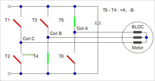
Alternative Power Switching (Rotation Control Circuit)


Comments
Please log in or sign up to comment.