


![u-GSM w. BG95-M3 - low power LTE CATM + NBIoT [NB1 + NB2] + eGPRS IoT global modem (uFL) + GNSS, RaspberryPI, Beaglebone and Arduino compatible shield](https://hackster.imgix.net/uploads/attachments/1575016/u-GSM_BG95Mx_1024px.jpg?auto=compress%2Cformat&w=48&h=48&fit=fill&bg=ffffff)
![u-GSM w. BG95-M2 - low power LTE CATM + NBIoT [NB1 + NB2] IoT global modem (uFL) + GNSS, RaspberryPI, Beaglebone and Arduino compatible shield](https://hackster.imgix.net/uploads/attachments/1575025/u-GSM_BG95Mx_1024px.jpg?auto=compress%2Cformat&w=48&h=48&fit=fill&bg=ffffff)

This notes refers how to interface the PocketBeagle board with itbrainpower.net u-GSM family modem.
The u-GSM modem family consist in around ~22 modem types having RPI and BeagleBone Black P9 interfaces embedded.
- PocketBeagle SBC
- any u-GSM modem uFL version (excepting BC95G version*) or
- any first version of ITBP modular modem (c-uGSM, h-nanoGSM, d-u3G or l-LTE **),
and mandatory one of the following:
- 1pcs. x LiPo battery [3.7V, > 250mA]***, or
- 1pcs. x super-capacitor for itbrainpower.net modems***.
* BC95G (do not be confused with BG95-M2 or BG95-M3) does not have ppp support included.
** first generation itbrainpower modular modems does not have P9 interface integrated, but still can be interfaced with BBB using wires.
I stress you again! LiPo/LiION battery OR super-capacitor are REQUIRED for proper u-GSM functionality! *** *** for low power LTE u-GSM modems used in LTE-CATM or NBIoT mode only [BG95-M2 and BG96/BG95-M3 having 2G mode restricted], the LiPO battery or the super-capacitor can be safely replaced with 1000-1500uF/6.3V LOW ESR capacitor.
Knowledge and skills required- PocketBeagle / BeagleBone Black hardware experience,
- Soldering
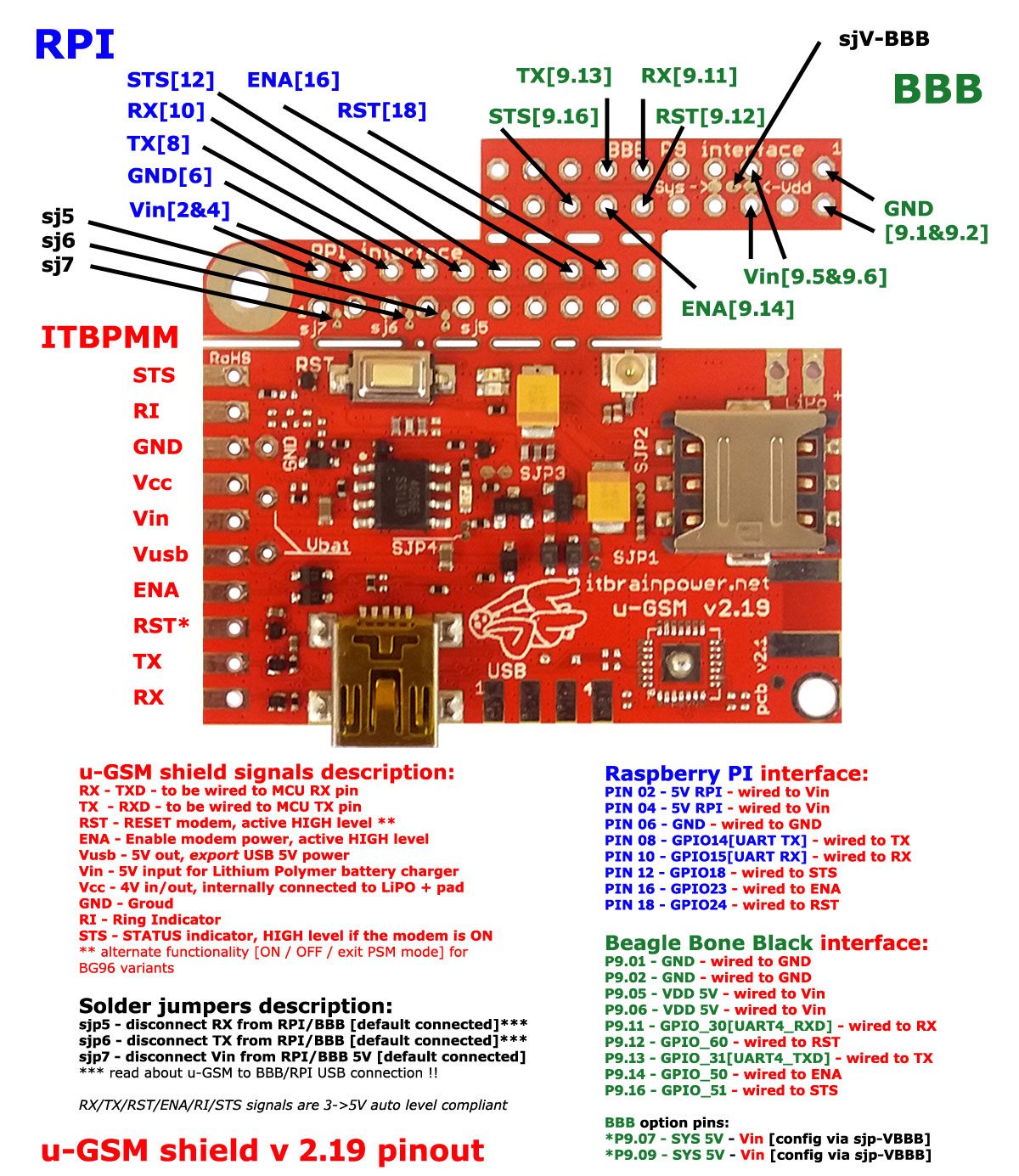
u-GSM BBB embedded P9 interface
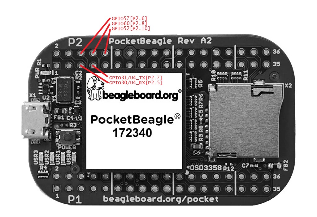
Condensed PocketBeagle P2 interface [only pins involved in interfacing with the u-GSM modem]
To identify all GPIO pins, you may like to take a look at PocketBeagle GPIO headers P1 and P2 - pinout.
Prepare the u-GSM modem for usageSolder the LiPO/LiION battery connector or the super-capacitor as shown in BBB/RPI u-GSM hardware integration post.
HINT: for low power LTE modems used in LTE-CATM or NBIoT mode only [BG95-M2 and BG96/BG95-M3 having 2G mode restricted], the LiPO battery or the super-capacitor can be safely replaced with 1000-1500uF/6.3V LOW ESR capacitor.
Hardware information for u-GSM modem interfacing [map interfacing]Logical pins - simply connect as shown bellow:
u-GSM modem BBB int. P9.16 [GPIO51] <====> PocketBeagle P2.10 [GPIO52]
u-GSM modem BBB int. P9.14 [GPIO50] <====> PocketBeagle P2.08 [GPIO60]
u-GSM modem BBB int. P9.12 [GPIO60] <====> PocketBeagle P2.06 [GPIO57]
u-GSM modem BBB int. P9.13 [GPIO31] <====> PocketBeagle P2.07 [UART4 TX / GPIO31]
u-GSM modem BBB int. P9.11 [GPIO30] <====> PocketBeagle P2.05 [UART4 RX / GPIO30]
Power supply pins - read PocketBeagle docs!!!!
u-GSM modem BBB interface BBB P9.01 [GND] <====> PocketBeagle GND
u-GSM modem BBB interface BBB P9.05  [5V] <====> PocketBeagle VIN / VOUT
That's all about hardware interfacing.
Linux Debian 10 how toSimply port the DEBIAN 10 section from BeagleBone Black Debian 10 howto to PocketBeagle using the ports mapping bellow.
BeagleBone Black =====> PocketBeagle

P9.14 [GPIO50]   =====> P2.08 [GPIO60]
P9.12 [GPIO60]   =====> P2.06 [GPIO57]
P9.13 [GPIO31]   =====> P2.07 [GPIO31]
P9.11 [GPIO30]   =====> P2.05 [GPIO30]
HINT: the PocketBeagle serial port dedicated for communication with the u-GSM modem remains available as /dev/ttyO4.
Useful PocketBlack references.- PocketBeagle wiki
- PocketBeagle GPIOs
- PocketBeagle reference manual
- PocketBeagle (Debian 10.3) images
- and last, but not least OSD3358 system in package
Keep calm, understand what's under the PocketBeagle blanket, follow the principles presented above and maybe write your own overlay!?
TUTORIAL & SOFTWARE ARE PROVIDED WITHOUT ANY WARRANTY!!! USE IT AT YOUR OWN RISK!!!!


Comments
Please log in or sign up to comment.