Operational amplifiers are awesome, they are used to design a lot of circuits. And has a wide applications in electronics. Today we are talking about the one little feature of operational amplifier is open loop gain condition, which is operational amplifier as a comparator. This mode of operational amplifier is used to compare the two inputs (analog) at the inverting and non-inverting terminal and then to give the stable output. You can order the digital trainer kit PCB made by me, from where you will find a lot of features like dual input-outputs, power supplies frequency generator and more. Order 5 pieces of 2-layer PCB in just $2 using JLCPCB prototyping service.
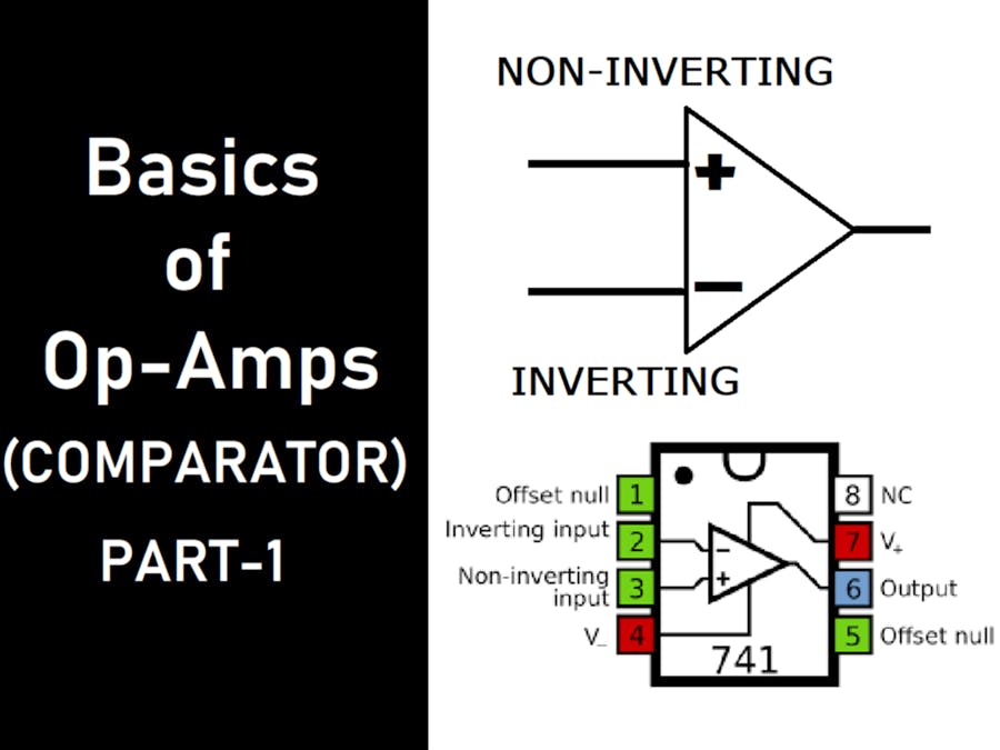
Operational amplifier has two terminals which are known as inverting and non-inverting. Inverting terminal is represented by minus and non-inverting by a plus. There is a phase shift of 180 degrees at the minus terminal and hence referred as inverting.
The open loop gain of an operational amplifier is in the order of Mega. Quite high values but the overall output is then restricted by the supply. At this voltage the output becomes saturated which is known as +Vsat and -Vsat in an operational amplifier.
Let’s talk more about this saturation and open loop gain. You can see here a basic diagram of the operational amplifier. This one has 5 terminals, 2 are the main plus minus signal input( Non-inverting and Inverting), there is one output and 2 power inputs. These power input terminals are known as +VCC and -VEE. Generally for simple single power supply use we can connect the -VEE to Ground. But practical solution of working is defining a 3rd terminal which is in the middle of two voltages (reference). Which may be discussed in next lectures of the same topic.
Now our circuit is completed, the output of a comparator is purely depended on the input. If the non-inverting input (plus) terminal is higher than inverting(minus) terminal then the output is active high. And in the opposite case, if the inverting one is high then the output of comparator is active low.
This active high and active low outputs of an operational amplifier is the supply voltage +VCC and -VEE. Because the gain is so high that the output wants to rise at max level. But can’t go above supply voltage and this termed as saturation. At this +VCC becomes +Vsat and -VCC becomes -Vsat.
These types of comparators are used to convert the analog signal into digital value. Let’s take an example of this configuration:
Let’s consider the inverting terminal of an operational amplifier is on a reference voltage of 2volts. Supply voltage is given 9V for +VCC and -9V for -VEE. Now we have an Analog time varying signal on the Non-inverting terminal, which can go at a peak of 4volts for some time t. Then the output of the comparator is defined as:
For time t signal at non-inverting terminal is higher than inverting terminal. That’s why the output of comparator goes up and saturated to +Vsat for that much of time and then come back to the normal level (-Vsat).
Digital Trainer KIT:I recently made this digital kit which has 8 bit digital input and output. It works on a dual rail voltage power supply directly from the center tapped transformer. Having on board BCD to 7 segment decoder, a small breadboard, 5v linear regulator and a programmable pulse generator.
This is the first version of kit and hope you will like this download the Gerber files from here. I will publish the full review and assembly in an another tutorial. You can use JLCPCB PCB prototyping and SMT assembly service to order the PCB. Register using this link to JLCPCB and get $54 new user coupons.


Comments
Please log in or sign up to comment.